
 Tiếng Việt
 ភាសាខ្មែរ
A copper flange is a type of industrial accessory made of copper, brass, etc. used to install and connect systems. Copper flanges have many applications in industries such as chemicals, petroleum, energy, water, etc. So what are the structures, specifications, and types of copper flanges? Let’s find out in this article.
What is a copper flange?
A copper flange is an industrial accessory made of copper materials, which can be copper, brass, etc., and is often used to connect pipes, industrial valves, pumps, etc. to create a complete piping system.
On the market today, there are many types of copper flanges. However, the most popular and widely used types are solid (blind) copper flanges, hollow copper flanges, ribbed copper flanges, etc.

Structure of a copper flange
- Bolt hole
- Inner diameter. This is the large gap in the middle of the flange.
- Outer diameter. This is the distance between the two opposite edges of each flange.

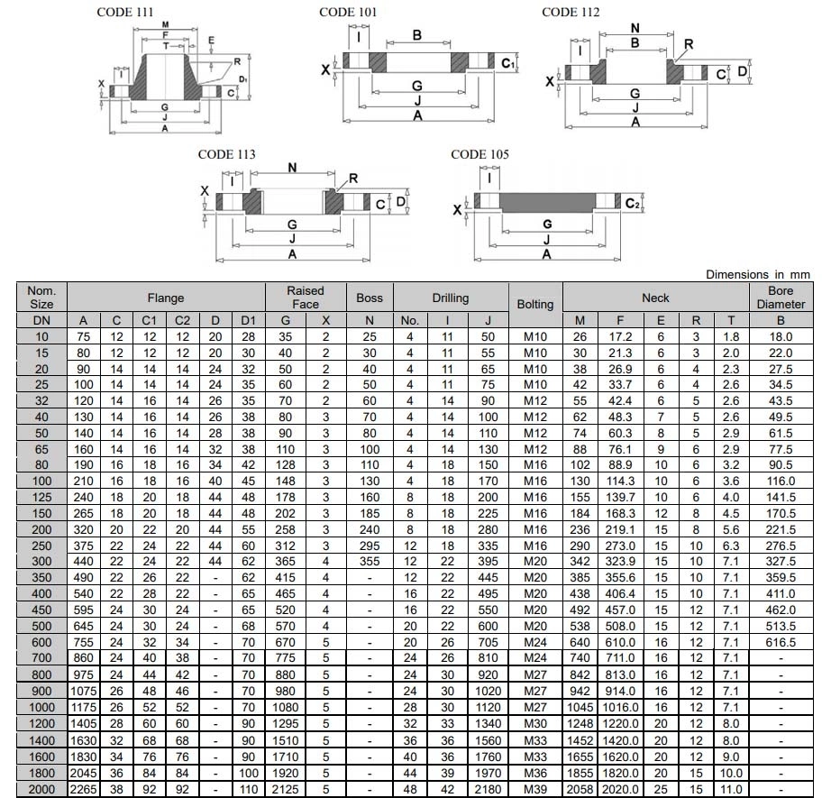
Technical specifications of copper flanges
Specification of copper flange
- Manufacturing materials: brass, red copper,…
- Size: DN50, DN65, DN80, DN100, DN125, DN150, DN200, DN250, DN300,…
- Flange production standards: JIS, BS, ANSI, DIN,…
- Working pressure: JIS 5K, 10K, 16K. 20K, PN6, PN10, PN16, PN25,
- Working environment: domestic water, clean water,…
- Origin: Vietnam, China, Japan,…
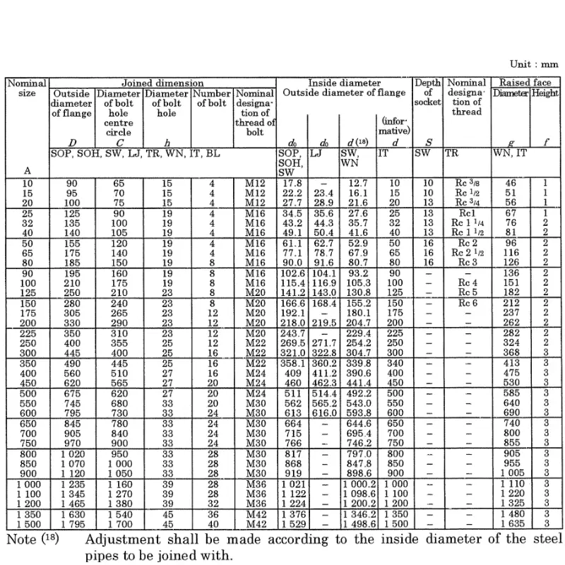
Technical data sheet of Copper Flange
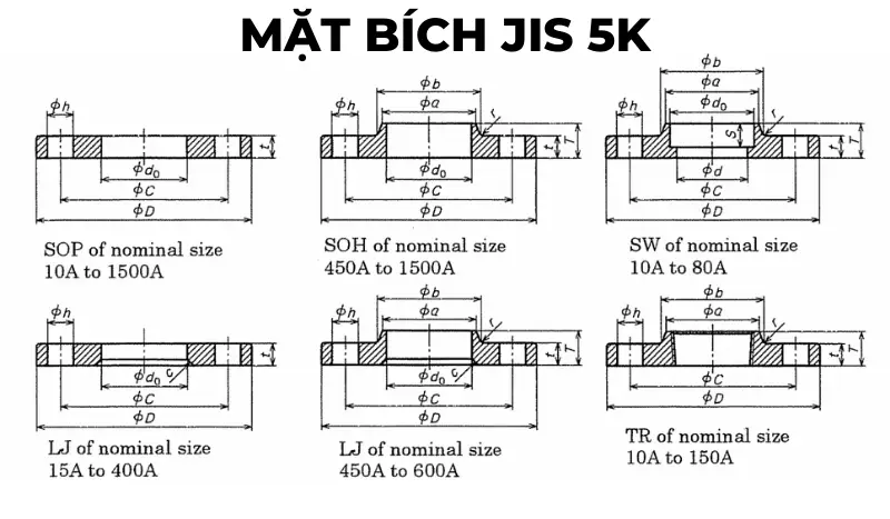
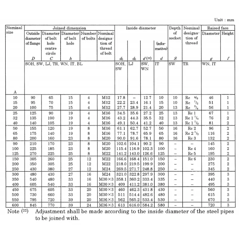
JIS 5K flange standard specifications

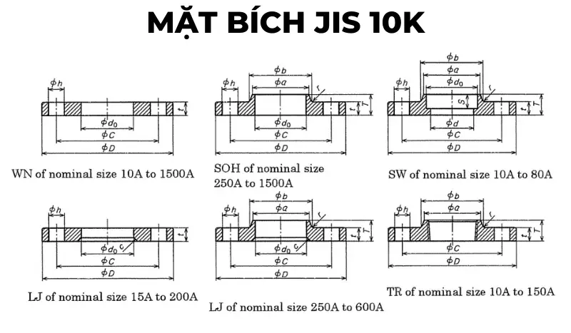
JIS 10K flange standard specifications
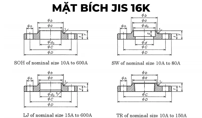
JIS 16K flange standard specifications
JIS 20K flange standard specifications


Flange specifications are manufactured according to DIN standards
Flange standard specifications DIN 2576 – PN6
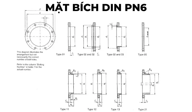
DIN PN6 flange technical data sheet
| DN | LINK DETAILS | OUTSIDE DIAMETER OF WELDING NECK | ĐƯỜNG KÍNH LỖ | FLANGE THICKNESS | Beveled face | CHECK CONNECTOR THICKNESS | WELD SURFACE DIAMETER | LENGTH | WELD NECK DIAMETER | CONNECTOR BELT ANGLE | WELD NECK THICKNESS | |||||||||||
|---|---|---|---|---|---|---|---|---|---|---|---|---|---|---|---|---|---|---|---|---|---|---|
| Outer diameter | Diameter of bolt circle | Bolt hole diameter | Bolt | |||||||||||||||||||
| D | K | L | Quantity | Size | A | B1 | B2 | C1 | C2 C3 |
C4 | E | F | G max | H1 | H2 | H3 | N1 | N2 | N3 | R1 | S | |
| Flange type | ||||||||||||||||||||||
| 01, 02, 05, 11, 12, 13, 21 | 11 21b |
01 12 32 |
2 | 01 02 |
11 12 13 21 |
5 | 2 | 32 | 5 | 12 13 |
11 | 11 | 11 | 12 13 |
21 | 11 12 13 21 |
11 | |||||
| 10 | 75 | 50 | 11 | 4 | M10 | 17,2 | 18 | 21 | 12 | 12 | 12 | 3 | 10 | – | 20 | 28 | 6 | 26 | 25 | 20 | 4 | 1,8 |
| 15 | 80 | 55 | 11 | 4 | M10 | 21,3 | 22 | 25 | 12 | 12 | 12 | 3 | 10 | – | 20 | 30 | 6 | 30 | 30 | 26 | 4 | 2 |
| 20 | 90 | 65 | 11 | 4 | M10 | 26,9 | 27,5 | 31 | 14 | 14 | 14 | 4 | 10 | – | 24 | 32 | 6 | 38 | 40 | 34 | 4 | 2,3 |
| 25 | 100 | 75 | 11 | 4 | M10 | 33,7 | 34,5 | 38 | 14 | 14 | 14 | 4 | 10 | – | 24 | 35 | 6 | 42 | 50 | 44 | 4 | 2,6 |
| 32 | 120 | 90 | 14 | 4 | M12 | 42,4 | 43,5 | 46 | 16 | 14 | 14 | 5 | 10 | – | 26 | 35 | 6 | 55 | 60 | 54 | 6 | 2,6 |
| 40 | 130 | 100 | 14 | 4 | M12 | 48,3 | 49,5 | 53 | 16 | 14 | 14 | 5 | 10 | – | 26 | 38 | 7 | 62 | 70 | 64 | 6 | 2,6 |
| 50 | 140 | 110 | 14 | 4 | M12 | 60,3 | 61,5 | 65 | 16 | 14 | 14 | 5 | 12 | – | 28 | 38 | 8 | 74 | 80 | 74 | 6 | 2,9 |
| 65 | 160 | 130 | 14 | 4 | M12 | 76,1 | 77,5 | 81 | 16 | 14 | 14 | 6 | 12 | 55 | 32 | 38 | 9 | 88 | 100 | 94 | 6 | 2,9 |
| 80 | 190 | 150 | 18 | 4 | M16 | 88,9 | 90,5 | 94 | 18 | 16 | 16 | 6 | 12 | 70 | 34 | 42 | 10 | 102 | 110 | 110 | 8 | 3,2 |
| 100 | 210 | 170 | 18 | 4 | M16 | 114,3 | 116 | 120 | 18 | 16 | 16 | 6 | 14 | 90 | 40 | 45 | 10 | 130 | 130 | 130 | 8 | 3,6 |
| 125 | 240 | 200 | 18 | 8 | M16 | 139,7 | 141,5 | 145 | 20 | 18 | 18 | 6 | 14 | 115 | 44 | 48 | 10 | 155 | 160 | 160 | 8 | 4 |
| 150 | 265 | 225 | 18 | 8 | M16 | 168,3 | 170,5 | 174 | 20 | 18 | 18 | 6 | 14 | 140 | 44 | 48 | 12 | 184 | 185 | 182 | 10 | 4,5 |
| 200 | 320 | 280 | 18 | 8 | M16 | 219,1 | 221,5 | 226 | 22 | 20 | 20 | 6 | 16 | 190 | 44 | 55 | 15 | 236 | 240 | 238 | 10 | 6,3 |
| 250 | 375 | 335 | 18 | 12 | M16 | 273 | 276,5 | 281 | 24 | 22 | 22 | 8 | 18 | 235 | 44 | 60 | 15 | 290 | 295 | 284 | 12 | 6,3 |
| 300 | 440 | 395 | 22 | 12 | M20 | 323,9 | 327,5 | 333 | 24 | 22 | 22 | 8 | 18 | 285 | 44 | 62 | 15 | 342 | 355 | 342 | 12 | 7,1 |
| 350 | 490 | 445 | 22 | 12 | M20 | 355,6 | 359,5 | 365 | 26 | 22 | 22 | 8 | 18 | 330 | – | 62 | 15 | 385 | – | 392 | 12 | 7,1 |
| 400 | 540 | 495 | 22 | 16 | M20 | 406,4 | 411 | 416 | 28 | 22 | 22 | 8 | 20 | 380 | – | 65 | 15 | 438 | – | 442 | 12 | 7,1 |
| 450 | 595 | 550 | 22 | 16 | M20 | 457 | 462 | 467 | 30 | 22 | 24 | 8 | 20 | 425 | – | 65 | 15 | 492 | – | 494 | 12 | 7,1 |
Flange standard specifications DIN 2576 – PN10
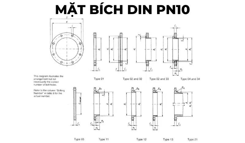
DIN PN10 flange technical data sheet
| DN | LINK DETAILS | OUTSIDE DIAMETER OF WELDING NECK | DIAMETER HOLE | FLANGE THICKNESS | Beveled face | CONNECTOR THICKNESS | WELD SURFACE DIAMETER | LENGTH | WELD NECK DIAMETER | CONNECTOR BELT ANGLE | WELD NECK THICKNESS | |||||||||||||
|---|---|---|---|---|---|---|---|---|---|---|---|---|---|---|---|---|---|---|---|---|---|---|---|---|
| Outer diameter | Bolt circle diameter | Bolt hole diameter | Bolt | |||||||||||||||||||||
| D | K | L | Quantity | Size | A | B1 | B2 | B3 | C1 | C2 | C3 | C4 | E | F | G max | H1 | H2 | H3 | N1 | N2 | N3 | R1 | S | |
| Flange type | ||||||||||||||||||||||||
| 01, 02, 04, 05, 11, 12, 13, 21 | 11 21 34 |
01 12 32 |
2 | 4 | 01 02 04 |
11 12 13 |
21 | 5 | 02 04 |
32 34 |
5 | 12 13 |
11 14 |
11 14 |
11 14 |
12 13 |
21 | 11 12 13 21 |
11 34 |
|||||
| 10 to 40 | Use pressure level PN40 | |||||||||||||||||||||||
| 50 to 150 | Use pressure level PN16 | |||||||||||||||||||||||
| 200 | 340 | 295 | 22 | 8 | M20 | 219,1 | 221,5 | 226 | 240 | 24 | 24 | 24 | 24 | 6 | 20 | 190 | 44 | 62 | 16 | 234 | 246 | 246 | 10 | 6,3 |
| 250 | 395 | 350 | 22 | 12 | M20 | 273 | 276,5 | 281 | 294 | 26 | 26 | 26 | 26 | 8 | 22 | 235 | 46 | 68 | 16 | 292 | 298 | 298 | 12 | 6,3 |
| 300 | 445 | 400 | 22 | 12 | M20 | 323,9 | 327,5 | 333 | 348 | 26 | 26 | 26 | 26 | 8 | 22 | 285 | 46 | 68 | 16 | 342 | 350 | 348 | 12 | 7,1 |
| 350 | 505 | 460 | 22 | 16 | M20 | 355,6 | 359,5 | 365 | 400 | 28 | 26 | 26 | 26 | 8 | 22 | 330 | 53 | 68 | 16 | 385 | 400 | 408 | 12 | 7,1 |
| 400 | 565 | 515 | 26 | 16 | M24 | 406,4 | 411 | 416 | 450 | 32 | 26 | 26 | 26 | 8 | 24 | 380 | 57 | 72 | 16 | 440 | 456 | 456 | 12 | 7,1 |
| 450 | 615 | 565 | 26 | 20 | M24 | 457 | 462 | 467 | 498 | 36 | 28 | 28 | 28 | 8 | 24 | 425 | 63 | 72 | 16 | 488 | 502 | 502 | 12 | 7,1 |
| 500 | 670 | 620 | 26 | 20 | M24 | 508 | 513,5 | 519 | 550 | 38 | 28 | 28 | 28 | 8 | 26 | 475 | 67 | 75 | 16 | 542 | 559 | 559 | 12 | 7,1 |
| 600 | 780 | 725 | 30 | 20 | M27 | 610 | 616,5 | 622 | 650 | 42 | 28 | 34 | 34 | 8 | 26 | 575 | 75 | 80 | 18 | 642 | 658 | 658 | 12 | 7,1 |
| 700 | 895 | 840 | 30 | 24 | M27 | 711 | 30 | 34 | 38 | 670 | 80 | 18 | 746 | 772 | 12 | 8 | ||||||||
| 800 | 1015 | 950 | 33 | 24 | M30 | 813 | 32 | 36 | 42 | 770 | 90 | 18 | 850 | 876 | 12 | 8 | ||||||||
| 900 | 1115 | 1050 | 33 | 28 | M30 | 914 | 34 | 38 | 46 | 860 | 95 | 20 | 950 | 976 | 12 | 10 | ||||||||
| 1000 | 1230 | 1160 | 36 | 28 | M33 | 1016 | 34 | 38 | 52 | 960 | 95 | 20 | 1052 | 1080 | 16 | 10 | ||||||||
| 1200 | 1455 | 1380 | 39 | 32 | M36 | 1219 | 38 | 44 | 60 | 1160 | 115 | 25 | 1256 | 1292 | 16 | 11 | ||||||||
| 1400 | 1675 | 1590 | 42 | 36 | M39 | 1422 | 42 | 48 | 120 | 25 | 1460 | 1496 | 16 | 12 | ||||||||||
| 1600 | 1915 | 1820 | 48 | 40 | M45 | 1626 | 46 | 52 | 130 | 25 | 1666 | 1712 | 16 | 14 | ||||||||||
| 1800 | 2115 | 2020 | 48 | 44 | M45 | 1829 | 50 | 56 | 140 | 30 | 1868 | 1910 | 16 | 15 | ||||||||||
| 2000 | 2325 | 2230 | 48 | 48 | M45 | 2032 | 54 | 60 | 150 | 30 | 2072 | 2120 | 16 | 16 | ||||||||||
| 2200 | 2550 | 2440 | 56 | 52 | M52 | 2235 | 58 | 160 | 35 | 2275 | 18 | 18 | ||||||||||||
| 2400 | 2760 | 2650 | 56 | 56 | M52 | 2438 | 62 | 170 | 35 | 2478 | 18 | 20 | ||||||||||||
| 2600 | 2960 | 2850 | 56 | 60 | M52 | 2620 | 66 | 180 | 40 | 2680 | 18 | 22 | ||||||||||||
| 2800 | 3180 | 3070 | 56 | 64 | M52 | 2820 | 70 | 190 | 40 | 2882 | 18 | 22 | ||||||||||||
| 3000 | 3405 | 3290 | 62 | 68 | M56 | 3020 | 75 | 200 | 45 | 3085 | 18 | 24 | ||||||||||||
Flange standard specifications: DIN 2544-PN16

DIN PN16 flange technical data sheet
| DN | LINK DETAILS | OUTSIDE DIAMETER OF WELDING NECK | DIAMETER HOLE | FLANGE THICKNESS | Beveled face | CONNECTOR THICKNESS | DIAMETER OF WELDING SURFACE | LENGTH | WELD NECK DIAMETER | CONNECTOR BELT ANGLE | WELD NECK THICKNESS | |||||||||||||
|---|---|---|---|---|---|---|---|---|---|---|---|---|---|---|---|---|---|---|---|---|---|---|---|---|
| Outer diameter | Bolt circle diameter | Bolt hole diameter | Bolt | |||||||||||||||||||||
| D | K | L | Quantity | Size | A | B1 | B2 | B3 | C1 | C2 | C3 | C4 | E | F | G max | H1 | H2 | H3 | N1 | N2 | N3 | R1 | S | |
| Flange type | ||||||||||||||||||||||||
| 01, 02, 04, 05, 11, 12, 13, 21 | 11 21 34 |
01 12 32 |
2 | 4 | 01 02 04 |
11 12 13 |
21 | 5 | 02 04 |
32 34 |
5 | 12 13 |
11 14 |
11 14 |
11 14 |
12 13 |
21 | 11 12 13 21 |
11 34 |
|||||
| 10 to 40 | Use PN40 pressure level flange | |||||||||||||||||||||||
| 50 | 165 | 125 | 18 | 4 | M16 | 60,3 | 61,5 | 65 | 77 | 19 | 18 | 18 | 18 | 5 | 16 | 28 | 45 | 8 | 74 | 84 | 84 | 5 | 2,9 | |
| 65 | 185 | 145 | 18 | 8 | M16 | 76,1 | 77,5 | 81 | 96 | 20 | 18 | 18 | 18 | 6 | 16 | 55 | 32 | 45 | 10 | 92 | 104 | 104 | 6 | 2,9 |
| 80 | 200 | 160 | 18 | 8 | M16 | 88,9 | 90,5 | 94 | 108 | 20 | 20 | 20 | 20 | 6 | 16 | 70 | 34 | 50 | 10 | 105 | 118 | 120 | 6 | 3,2 |
| 100 | 220 | 180 | 18 | 8 | M16 | 114,3 | 116 | 120 | 134 | 22 | 20 | 20 | 20 | 6 | 18 | 90 | 40 | 52 | 12 | 131 | 140 | 140 | 8 | 3,6 |
| 125 | 250 | 210 | 18 | 8 | M16 | 139,7 | 141,5 | 145 | 162 | 22 | 22 | 22 | 22 | 6 | 18 | 115 | 44 | 55 | 12 | 156 | 168 | 170 | 8 | 4 |
| 150 | 285 | 240 | 22 | 8 | M20 | 168,3 | 170,5 | 174 | 188 | 24 | 22 | 22 | 22 | 6 | 20 | 140 | 44 | 55 | 12 | 184 | 195 | 190 | 10 | 4,5 |
| 200 | 340 | 295 | 22 | 12 | M20 | 219,1 | 221,5 | 226 | 240 | 26 | 24 | 24 | 24 | 6 | 20 | 190 | 44 | 62 | 16 | 235 | 246 | 246 | 10 | 6,3 |
| 250 | 405 | 355 | 26 | 12 | M24 | 273 | 276,5 | 281 | 294 | 29 | 26 | 26 | 26 | 8 | 22 | 235 | 46 | 70 | 16 | 292 | 298 | 296 | 12 | 6,3 |
| 300 | 460 | 410 | 26 | 12 | M24 | 323,9 | 327,5 | 33 | 348 | 32 | 28 | 28 | 28 | 8 | 24 | 285 | 46 | 78 | 16 | 344 | 350 | 350 | 12 | 7,1 |
| 350 | 520 | 470 | 26 | 16 | M24 | 355,6 | 359 | 365 | 400 | 35 | 30 | 30 | 30 | 8 | 26 | 330 | 57 | 82 | 16 | 390 | 400 | 410 | 12 | 8 |
| 400 | 580 | 525 | 30 | 16 | M27 | 406,4 | 411 | 416 | 454 | 38 | 32 | 32 | 32 | 8 | 28 | 380 | 63 | 85 | 16 | 445 | 456 | 458 | 12 | 8 |
| 450 | 640 | 585 | 30 | 20 | M27 | 457 | 462 | 467 | 500 | 42 | 40 | 40 | 40 | 8 | 30 | 425 | 68 | 87 | 16 | 490 | 502 | 516 | 12 | 8 |
| 500 | 715 | 650 | 33 | 20 | M30 | 508 | 513,5 | 510 | 556 | 46 | 44 | 44 | 44 | 8 | 32 | 475 | 73 | 90 | 16 | 548 | 559 | 576 | 12 | 8 |
| 600 | 840 | 770 | 36 | 20 | M33 | 610 | 616,5 | 622 | 660 | 52 | 54 | 54 | 54 | 8 | 32 | 575 | 83 | 95 | 18 | 652 | 658 | 690 | 12 | 8,8 |
| 700 | 910 | 840 | 36 | 24 | M33 | 711 | 36 | 42 | 48 | 670 | 83 | 100 | 18 | 755 | 760 | 760 | 12 | 8,8 | ||||||
| 800 | 1025 | 950 | 39 | 24 | M36 | 813 | 38 | 42 | 52 | 770 | 90 | 105 | 20 | 855 | 864 | 862 | 12 | 10 | ||||||
| 900 | 1125 | 1050 | 39 | 28 | M36 | 914 | 40 | 44 | 58 | 860 | 94 | 110 | 20 | 955 | 968 | 962 | 12 | 10 | ||||||
| 1000 | 1255 | 1170 | 42 | 28 | M39 | 1016 | 42 | 46 | 64 | 960 | 100 | 120 | 22 | 1058 | 1072 | 1070 | 16 | 10 | ||||||
| 1200 | 1485 | 1390 | 48 | 32 | M45 | 1219 | 48 | 52 | 76 | 1160 | 130 | 30 | 1262 | 1282 | 16 | 12,5 | ||||||||
| 1400 | 1685 | 1590 | 48 | 36 | M45 | 1422 | 52 | 58 | 1346 | 145 | 30 | 1465 | 1482 | 16 | 14,2 | |||||||||
| 1600 | 1930 | 1820 | 56 | 40 | M52 | 1626 | 58 | 64 | 1546 | 160 | 35 | 1668 | 1696 | 16 | 16 | |||||||||
| 1800 | 2130 | 2020 | 56 | 44 | M52 | 1829 | 62 | 68 | 1746 | 170 | 35 | 1870 | 1896 | 16 | 17,5 | |||||||||
| 2000 | 2345 | 2230 | 62 | 48 | M56 | 2032 | 66 | 70 | 1950 | 180 | 40 | 2072 | 2100 | 16 | 20 | |||||||||
Flange standard specifications: DIN 2544-PN25
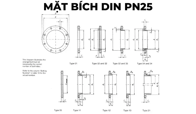
DIN PN25 flange technical data sheet
| DN | LINK DETAILS | OUTSIDE DIAMETER OF WELDING NECK | DIAMETER HOLE | FLANGE THICKNESS | Beveled face | CONNECTOR THICKNESS | WELD SURFACE DIAMETER | LENGTH | WELD NECK DIAMETER | CONNECTOR BELT ANGLE | WELD NECK THICKNESS | |||||||||||||
|---|---|---|---|---|---|---|---|---|---|---|---|---|---|---|---|---|---|---|---|---|---|---|---|---|
| Outer diameter | Bolt circle diameter | Bolt hole diameter | Bolt | |||||||||||||||||||||
| D | K | L | Quantity | Size | A | B1 | B2 | B3 | C1 | C2 | C3 | C4 | E | F | G max | H1 | H2 | H3 | N1 | N2 | N3 | R1 | S | |
| Flange type | ||||||||||||||||||||||||
| 01, 02, 04, 05, 11, 12, 13, 21 | 11 21 34 |
01 12 32 |
2 | 4 | 01 02 04 |
11 12 13 |
21 | 5 | 02 04 |
32 34 |
5 | 12 13 |
11 14 |
11 14 |
11 14 |
12 13 |
21 | 11 12 13 21 |
11 34 |
|||||
| 10 to 150 | Use flanges with pressure class PN40 | |||||||||||||||||||||||
| 200 | 360 | 310 | 26 | 12 | M24 | 219,1 | 221,5 | 226 | 250 | 32 | 30 | 30 | 30 | 6 | 26 | 190 | 52 | 80 | 16 | 244 | 256 | 252 | 10 | 6,3 |
| 250 | 425 | 370 | 30 | 12 | M27 | 273 | 276,5 | 281 | 302 | 35 | 32 | 32 | 32 | 8 | 26 | 235 | 60 | 88 | 18 | 298 | 310 | 304 | 12 | 7,1 |
| 300 | 485 | 430 | 30 | 16 | M27 | 323,9 | 327,5 | 333 | 356 | 38 | 34 | 34 | 34 | 8 | 28 | 285 | 67 | 92 | 18 | 352 | 364 | 364 | 12 | 8 |
| 350 | 555 | 490 | 33 | 16 | M30 | 355,6 | 359,5 | 365 | 408 | 42 | 38 | 38 | 38 | 8 | 32 | 332 | 72 | 100 | 20 | 398 | 418 | 418 | 12 | 8 |
| 400 | 620 | 550 | 36 | 16 | M33 | 406,4 | 411 | 416 | 462 | 46 | 40 | 40 | 40 | 8 | 34 | 380 | 78 | 110 | 20 | 452 | 472 | 472 | 12 | 8,8 |
| 450 | 670 | 600 | 36 | 20 | M33 | 457 | 462 | 467 | 510 | 50 | 46 | 46 | 46 | 8 | 36 | 425 | 84 | 110 | 20 | 500 | 520 | 520 | 12 | 8,8 |
| 500 | 730 | 660 | 36 | 20 | M33 | 508 | 513,5 | 519 | 568 | 56 | 48 | 48 | 48 | 8 | 38 | 475 | 90 | 125 | 20 | 558 | 580 | 580 | 12 | 10 |
| 600 | 845 | 770 | 39 | 20 | M36 | 610 | 616,5 | 622 | 670 | 68 | 58 | 58 | 58 | 8 | 40 | 575 | 100 | 125 | 20 | 660 | 684 | 684 | 12 | 11 |
| 700 | 960 | 875 | 42 | 24 | M39 | 711 | 46 | 50 | 125 | 20 | 760 | 780 | 12 | 12,5 | ||||||||||
| 800 | 1085 | 990 | 48 | 24 | M45 | 813 | 50 | 54 | 135 | 22 | 864 | 882 | 12 | 14,2 | ||||||||||
| 900 | 1185 | 1090 | 48 | 28 | M45 | 914 | 54 | 58 | 145 | 24 | 968 | 982 | 12 | 16 | ||||||||||
| 1000 | 1320 | 1210 | 56 | 28 | M52 | 1016 | 58 | 62 | 155 | 24 | 1070 | 1086 | 16 | 17,5 | ||||||||||
| 1200 | 1530 | 1420 | 56 | 32 | M52 | 1219 | 70 | 1296 | 18 | |||||||||||||||
| 1400 | 1755 | 1640 | 62 | 36 | M56 | 1422 | 76 | 1508 | 18 | |||||||||||||||
| 1600 | 1975 | 1860 | 62 | 40 | M56 | 1626 | 84 | 1726 | 20 | |||||||||||||||
| 1800 | 2195 | 2070 | 70 | 44 | M64 | 1829 | 90 | 1920 | 20 | |||||||||||||||
| 2000 | 2425 | 2300 | 70 | 48 | M64 | 2032 | 96 | 2150 | 20 | |||||||||||||||
Flange standard specifications: DIN 2544-PN40
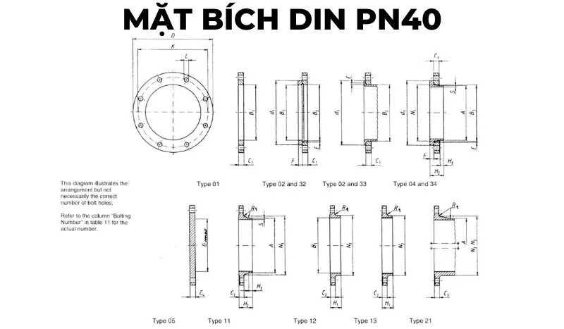
DIN PN40 flange technical data sheet
| DN | LINK DETAILS | OUTSIDE DIAMETER OF WELDING NECK | DIAMETER HOLE | FLANGE THICKNESS | Beveled face | CONNECTOR THICKNESS | WELD SURFACE DIAMETER | LENGTH | WELD NECK DIAMETER | CONNECTOR BELT ANGLE | WELD NECK THICKNESS | |||||||||||||
|---|---|---|---|---|---|---|---|---|---|---|---|---|---|---|---|---|---|---|---|---|---|---|---|---|
| Outer diameter | Bolt circle diameter | Bolt hole diameter | Bolt | |||||||||||||||||||||
| D | K | L | Quantity | Size | A | B1 | B2 | B3 | C1 | C2 | C3 | C4 | E | F | G max | H1 | H2 | H3 | N1 | N2 | N3 | R1 | S | |
| Flange type | ||||||||||||||||||||||||
| 01, 02, 04, 05, 11, 12, 13, 21 | 11 21 34 |
01 12 32 |
2 | 4 | 01 02 04 |
11 12 13 |
21 | 5 | 02 04 |
32 34 |
5 | 12 13 |
11 14 |
11 14 |
11 14 |
12 13 |
21 | 11 12 13 21 |
11 34 |
|||||
| 10 | 90 | 60 | 14 | 4 | M12 | 17,2 | 18 | 21 | 31 | 14 | 16 | 16 | 16 | 3 | 12 | 22 | 35 | 6 | 28 | 30 | 28 | 4 | 1,8 | |
| 15 | 95 | 65 | 14 | 4 | M12 | 21,3 | 22 | 25 | 35 | 14 | 16 | 16 | 16 | 3 | 12 | 22 | 38 | 6 | 32 | 35 | 32 | 4 | 2 | |
| 20 | 105 | 75 | 14 | 4 | M12 | 26,9 | 27,5 | 31 | 42 | 16 | 18 | 18 | 18 | 4 | 14 | 26 | 40 | 6 | 40 | 45 | 40 | 4 | 2,3 | |
| 25 | 115 | 85 | 14 | 4 | M12 | 33,7 | 34,5 | 38 | 49 | 16 | 18 | 18 | 18 | 4 | 14 | 28 | 40 | 6 | 46 | 52 | 50 | 4 | 2,6 | |
| 32 | 140 | 100 | 18 | 4 | M16 | 42,4 | 43,5 | 47 | 59 | 18 | 18 | 18 | 18 | 5 | 14 | 30 | 42 | 6 | 56 | 60 | 60 | 6 | 2,6 | |
| 40 | 150 | 110 | 18 | 4 | M16 | 48,3 | 49,5 | 53 | 67 | 18 | 18 | 18 | 18 | 5 | 14 | 32 | 45 | 7 | 64 | 70 | 70 | 6 | 2,6 | |
| 50 | 165 | 125 | 18 | 4 | M16 | 60,3 | 61,5 | 65 | 77 | 20 | 20 | 20 | 20 | 5 | 16 | 34 | 48 | 8 | 75 | 84 | 84 | 6 | 2,9 | |
| 65 | 185 | 145 | 18 | 8 | M16 | 76,1 | 77,5 | 81 | 96 | 22 | 22 | 22 | 22 | 6 | 16 | 55 | 38 | 52 | 10 | 90 | 104 | 104 | 6 | 2,9 |
| 80 | 200 | 160 | 18 | 8 | M16 | 88,9 | 90,5 | 94 | 114 | 24 | 24 | 24 | 24 | 6 | 18 | 70 | 40 | 58 | 12 | 105 | 118 | 120 | 8 | 3,2 |
| 100 | 235 | 190 | 22 | 8 | M20 | 114,3 | 116 | 120 | 138 | 26 | 24 | 24 | 24 | 6 | 20 | 90 | 44 | 65 | 12 | 134 | 145 | 142 | 8 | 3,6 |
| 125 | 270 | 220 | 26 | 8 | M24 | 139,7 | 141,5 | 145 | 166 | 28 | 26 | 26 | 26 | 6 | 22 | 115 | 48 | 68 | 12 | 162 | 170 | 162 | 8 | 4 |
| 150 | 300 | 250 | 26 | 8 | M24 | 168,3 | 170,5 | 174 | 194 | 30 | 28 | 28 | 28 | 6 | 24 | 140 | 52 | 75 | 12 | 192 | 200 | 192 | 10 | 4,5 |
| 200 | 375 | 320 | 30 | 12 | M27 | 219,1 | 221,5 | 226 | 250 | 36 | 34 | 34 | 36 | 6 | 28 | 190 | 52 | 88 | 16 | 244 | 260 | 254 | 10 | 6,3 |
| 250 | 450 | 385 | 33 | 12 | M30 | 273 | 276,5 | 281 | 312 | 38 | 38 | 38 | 38 | 8 | 30 | 235 | 60 | 105 | 18 | 306 | 312 | 312 | 12 | 7,1 |
| 300 | 515 | 450 | 33 | 16 | M30 | 323,9 | 327,5 | 333 | 368 | 42 | 42 | 42 | 42 | 8 | 34 | 285 | 67 | 115 | 18 | 362 | 380 | 378 | 12 | 8 |
| 350 | 580 | 510 | 36 | 16 | M33 | 355,6 | 359,5 | 365 | 418 | 46 | 46 | 46 | 46 | 8 | 36 | 330 | 72 | 125 | 20 | 408 | 424 | 432 | 12 | 8,8 |
| 400 | 660 | 585 | 39 | 16 | M36 | 406,4 | 411 | 416 | 472 | 50 | 50 | 50 | 50 | 8 | 42 | 380 | 78 | 135 | 20 | 462 | 478 | 498 | 12 | 11 |
| 450 | 685 | 610 | 39 | 20 | M36 | 457 | 462 | 467 | 510 | 57 | 57 | 57 | 57 | 8 | 46 | 425 | 84 | 135 | 20 | 500 | 522 | 522 | 12 | 12,5 |
| 500 | 755 | 670 | 42 | 20 | M39 | 508 | 513,5 | 519 | 572 | 57 | 57 | 57 | 57 | 8 | 50 | 475 | 90 | 140 | 20 | 562 | 576 | 576 | 12 | 14,2 |
| 600 | 890 | 795 | 48 | 20 | M45 | 610 | 616,5 | 622 | 676 | 72 | 72 | 72 | 72 | 8 | 54 | 575 | 100 | 150 | 20 | 666 | 686 | 686 | 12 | 16 |
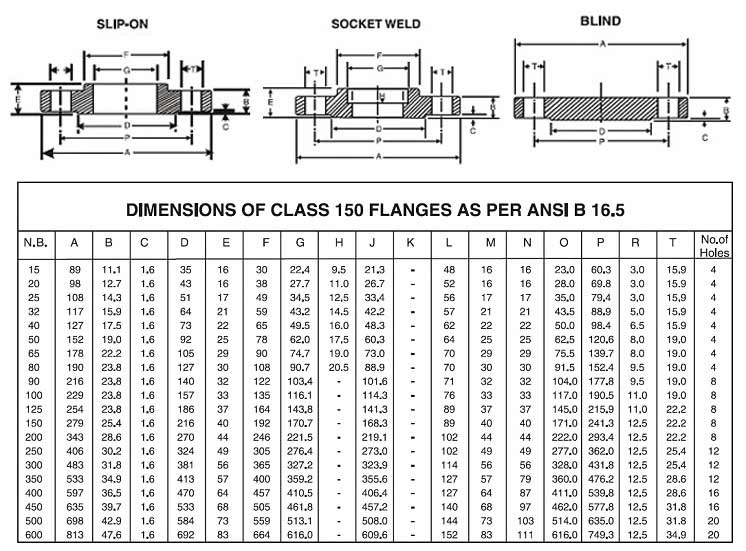
Flange standard specifications manufactured according to ANSI standards
ANSI 150 series flange standard specifications
ANSI 300 series flange standard specifications
 ??? In addition to the popular 150 and 300 series, ANSI flanges also have other series: 400, 600, 900, 1500, and 2500. You can see more in the table below (documents cited from the standard ASME/ANSI B16.10/19).
| CURRENT | TUBE SIZE (INCH) |
FLANGE OUTSIDE DIAMETER (MM) |
OUTSIDE DIAMETER OF PIPE (MM) |
NUMBER OF BULONG HOLES | BOLT HOLE DIAMETER (MM) |
BOLT CIRCLE (MM) |
|---|---|---|---|---|---|---|
| 400 Series | 1/2 | 57,2 | 21,3 | 4,0 | 15,9 | 34,9 |
| 3/4 | 85,7 | 26,7 | 4,0 | 19,1 | 69,9 | |
| 1 | 79,4 | 33,5 | 4,0 | 19,1 | 63,5 | |
| 1-1 / 4 | 120,7 | 42,2 | 4,0 | 19,1 | 54,0 | |
| 1-1 / 2 | 149,2 | 48,3 | 4,0 | 22,2 | 88,9 | |
| 2 | 139,7 | 60,5 | 8,0 | 19,1 | 127,0 | |
| 2-1 / 2 | 165,1 | 73,2 | 8,0 | 22,2 | 104,8 | |
| 3 | 196,9 | 88,9 | 8,0 | 22,2 | 136,5 | |
| 3-1 / 2 | 228,6 | 101,6 | 8,0 | 25,4 | 171,5 | |
| 4 | 254,0 | 114,3 | 8,0 | 25,4 | 181,0 | |
| 5 | 279,4 | 141,2 | 8,0 | 25,4 | 222,3 | |
| 6 | 292,1 | 168,4 | 12,0 | 25,4 | 238,1 | |
| số 8 | 381,0 | 219,2 | 12,0 | 22,2 | 330,2 | |
| 10 | 419,1 | 273,1 | 16,0 | 19,1 | 374,7 | |
| 12 | 495,3 | 323,9 | 16,0 | 15,9 | 412,8 | |
| 14 | 584,2 | 355,6 | 20,0 | 15,9 | 501,7 | |
| 16 | 622,3 | 406,4 | 20,0 | 12,7 | 546,1 | |
| 18 | 711,2 | 457,2 | 24,0 | 12,7 | 590,6 | |
| 20 | 749,3 | 508,0 | 24,0 | 9,5 | 685,8 | |
| 24 | 914,4 | 609,6 | 24,0 | 3,2 | 812,8 | |
| 600 Series | 1/2 | 57,2 | 21,3 | 4,0 | 15,9 | 34,9 |
| 3/4 | 85,7 | 26,7 | 4,0 | 19,1 | 69,9 | |
| 1 | 79,4 | 33,5 | 4,0 | 19,1 | 63,5 | |
| 1-1/4 | 120,7 | 42,2 | 4,0 | 19,1 | 54,0 | |
| 1-1/2 | 149,2 | 48,3 | 4,0 | 22,2 | 88,9 | |
| 2 | 139,7 | 60,5 | 8,0 | 19,1 | 127,0 | |
| 2-1/2 | 165,1 | 73,2 | 8,0 | 22,2 | 104,8 | |
| 3 | 196,9 | 88,9 | 8,0 | 22,2 | 136,5 | |
| 3-1/2 | 228,6 | 101,6 | 8,0 | 25,4 | 171,5 | |
| 4 | 235,0 | 114,3 | 8,0 | 25,4 | 190,5 | |
| 5 | 330,2 | 141,2 | 8,0 | 19,1 | 241,3 | |
| 6 | 355,6 | 168,4 | 12,0 | 19,1 | 266,7 | |
| 8 | 393,7 | 219,2 | 12,0 | 19,1 | 311,2 | |
| 10 | 508,0 | 273,1 | 16,0 | 15,9 | 431,8 | |
| 12 | 558,8 | 323,9 | 20,0 | 15,9 | 476,3 | |
| 14 | 565,2 | 355,6 | 20,0 | 12,7 | 489,0 | |
| 16 | 685,8 | 406,4 | 20,0 | 9,5 | 565,2 | |
| 18 | 730,3 | 457,2 | 20,0 | 6,4 | 616,0 | |
| 20 | 812,8 | 508,0 | 24,0 | 6,4 | 698,5 | |
| 24 | 939,8 | 609,6 | 24,0 | 50,8 | 838,2 | |
| 900 Series | 1/2 | 82,6 | 21,3 | 4,0 | 22,2 | 69,9 |
| 3/4 | 123,8 | 26,7 | 4,0 | 22,2 | 63,5 | |
| 1 | 104,8 | 33,5 | 4,0 | 25,4 | 101,6 | |
| 1-1/4 | 146,1 | 42,2 | 4,0 | 25,4 | 92,1 | |
| 1-1/2 | 177,8 | 48,3 | 4,0 | 22,2 | 79,4 | |
| 2 | 190,5 | 60,5 | 8,0 | 25,4 | 139,7 | |
| 2-1/2 | 212,7 | 73,2 | 8,0 | 22,2 | 165,1 | |
| 3 | 215,9 | 88,9 | 8,0 | 22,2 | 165,1 | |
| 4 | 266,7 | 114,3 | 8,0 | 19,1 | 222,3 | |
| 5 | 311,2 | 141,2 | 8,0 | 15,9 | 279,4 | |
| 6 | 381,0 | 168,4 | 12,0 | 19,1 | 292,1 | |
| 8 | 444,5 | 219,2 | 12,0 | 12,7 | 368,3 | |
| 10 | 520,7 | 273,1 | 16,0 | 12,7 | 444,5 | |
| 12 | 609,6 | 323,9 | 20,0 | 12,7 | 533,4 | |
| 14 | 628,7 | 355,6 | 20,0 | 9,5 | 558,8 | |
| 16 | 666,8 | 406,4 | 20,0 | 6,4 | 603,3 | |
| 18 | 787,4 | 457,2 | 20,0 | 50,8 | 685,8 | |
| 20 | 819,2 | 508,0 | 20,0 | 47,6 | 723,9 | |
| 24 | 1041,4 | 609,6 | 20,0 | 34,9 | 876,3 | |
| ANSI B16.5 covers only sizes through 24″ | ||||||
| 26 | 1047,8 | 20,0 | 28,6 | 927,1 | ||
| 28 | 1168,4 | 20,0 | 73,0 | 1009,7 | ||
| 30 | 1206,5 | 20,0 | 73,0 | 1047,8 | ||
| 32 | 1276,4 | 20,0 | 66,7 | 1130,3 | ||
| 34 | 1397,0 | 20,0 | 60,3 | 1212,9 | ||
| 36 | 1435,1 | 20,0 | 60,3 | 1251,0 | ||
| 1500 Series | 1/2 | 82,6 | 21,3 | 4,0 | 22,2 | 69,9 |
| 3/4 | 123,8 | 26,7 | 4,0 | 22,2 | 63,5 | |
| 1 | 104,8 | 33,5 | 4,0 | 25,4 | 101,6 | |
| 1-1/4 | 146,1 | 42,2 | 4,0 | 25,4 | 92,1 | |
| 1-1/2 | 177,8 | 48,3 | 4,0 | 22,2 | 79,4 | |
| 2 | 190,5 | 60,5 | 8,0 | 25,4 | 139,7 | |
| 2-1/2 | 212,7 | 73,2 | 8,0 | 22,2 | 165,1 | |
| 3 | 241,3 | 88,9 | 8,0 | 19,1 | 203,2 | |
| 4 | 285,8 | 114,3 | 8,0 | 15,9 | 215,9 | |
| 5 | 336,6 | 141,2 | 8,0 | 9,5 | 266,7 | |
| 6 | 368,3 | 168,4 | 12,0 | 12,7 | 292,1 | |
| 8 | 482,6 | 219,2 | 12,0 | 6,4 | 368,3 | |
| 10 | 584,2 | 273,1 | 12,0 | 50,8 | 482,6 | |
| 12 | 647,7 | 323,9 | 16,0 | 47,6 | 546,1 | |
| 14 | 723,9 | 355,6 | 16,0 | 41,3 | 635,0 | |
| 16 | 800,1 | 406,4 | 16,0 | 34,9 | 666,8 | |
| 18 | 914,4 | 457,2 | 16,0 | 28,6 | 749,3 | |
| 20 | 946,2 | 508,0 | 16,0 | 73,0 | 793,8 | |
| 24 | 1168,4 | 609,6 | 16,0 | 60,3 | 990,6 | |
| 2500 Series | 1/2 | 120,7 | 21,3 | 4,0 | 22,2 | 63,5 |
| 3/4 | 114,3 | 26,7 | 4,0 | 22,2 | 57,2 | |
| 1 | 146,1 | 33,5 | 4,0 | 25,4 | 95,3 | |
| 1-1/4 | 171,5 | 42,2 | 4,0 | 22,2 | 123,8 | |
| 1-1/2 | 203,2 | 48,3 | 4,0 | 19,1 | 108,0 | |
| 2 | 222,3 | 60,5 | 8,0 | 22,2 | 133,4 | |
| 2-1/2 | 241,3 | 73,2 | 8,0 | 19,1 | 158,8 | |
| 3 | 304,8 | 88,9 | 8,0 | 15,9 | 228,6 | |
| 4 | 355,6 | 114,3 | 8,0 | 9,5 | 235,0 | |
| 5 | 393,7 | 141,2 | 8,0 | 3,2 | 285,8 | |
| 6 | 482,6 | 168,4 | 8,0 | 47,6 | 342,9 | |
| 8 | 514,4 | 219,2 | 12,0 | 47,6 | 425,5 | |
| 10 | 647,7 | 273,1 | 12,0 | 34,9 | 527,1 | |
| 12 | 762,0 | 323,9 | 12,0 | 28,6 | 600,1 | |
Flange standard specifications BS 4504-EN 1092
Flange standard specifications BS 4504 PN6
Flange standard specifications BS 4504 PN10

Flange standard specifications BS 4504 PN16

Flange standard specifications BS 4504 PN25

Flange standard specifications BS 4504 PN40

Types of copper flanges
There are many types of flanges on the market today due to the different service conditions in which we operate. A copper flange is one of the top choices for accessories. So do you know how many types of copper surfaces there are? If not, then read on!

Blind copper flange (solid)
A blind copper flange (also known as a solid flange) is a type of flange without a hole in the middle. This product is used to seal pipes and equipment to prevent flow or change flow.
Hollow copper flange
Unlike blind copper flanges, hollow copper flanges are the type with a hole in the middle. This product is used to connect pipes or equipment of the same diameter for the purpose of maintaining continuous flow without changing the direction of flow.
Copper flange with burr
A ribbed copper flange is a type of flange with a protruding edge in the middle (ridged surface), the connection between the two flanges is a gasket made of brass. This product is often used in systems that require high tightness and can withstand great pressure.
=> See more: Common types of flanges on the market today
Advantages and disadvantages of copper flanges
Advantage

- Copper flanges can be used in clean water, domestic water, etc.
- Variety of sizes. Copper flanges are produced in many different sizes, suitable for many DN50–DN800 pipes.
- Flanges meet JIS, DIN, ANSI, and BS standards.
- Low cost. MB copper is cheaper than other types of flanges, specifically flanges made from carbon steel, stainless steel, etc.
- Efficient in installation and maintenance. Copper MB can be installed, replaced, and maintained easily.
The copper flange has many outstanding advantages; however, it also has some disadvantages, as follows:
Disadvantages
- Copper flanges should be limited in their use in chemical and highly corrosive environments.
- The connection is slow and takes time to integrate.
Application of a copper flange
Copper flanges have many applications in various industries, thanks to their features and advantages. Here are some common applications of copper flanges:
- In the water treatment system. Specifically, copper flange is used in the installation of water pipes, clean water supply and drainage, and domestic water in residential areas, public areas, factories, industries, etc.
- In the food industry. Copper flanges are used to connect pipes or equipment used for food processing and preservation.
- Used for installation with industrial valves. Such as copper ball valves, globe valves, copper gate valves, etc.
- In the energy industry. A copper flange is used to connect pipes or equipment involved in the production, transmission, and distribution of electricity, specifically generators, transformers, cables, etc.
How to choose a flange properly
Are you wondering, “How to choose a flange properly?”
In my personal opinion, to choose the right flange, it must meet the following basic criteria:
- Criteria 1: What type of flange standard should you choose? Such as production standards such as JIS, DIN, ANSI, BS, etc. If you choose the wrong standard, it will not be possible to connect with each other.
- Criteria 2. Do you need to determine what diameter the pipe is?
- Criteria 3. Selection of flange manufacturing materials
- Criteria 4: Determine the type of flange connection. For example, for threaded flanges, the type of weld connection is most convenient.
- Criteria 5. Need to choose blind flange, hollow flange, or flange with flange,…
- Criterion 6. This criterion is equally important, which is determining the size according to specifications.
That is the basic information about copper flanges—an effective and convenient industrial accessory. Bao Tin Steel hopes this article will help you better understand MB copper products. In addition, if you are interested in or need to buy flanges, please contact Bao Tin Steel Co., Ltd. for consulting and purchasing support.