
 Tiếng Việt
 ភាសាខ្មែរ
Giacomini Brass safety valve R140/R140M . series is used to prevent overpressure of the heater of the heating system, domestic water system (protection of hot water storage), and water system (cold water drainage). The valves comply with Pressure Directive “PED” 2014/68/UE.
Version and product code of Giacomini Brass safety valve R140/R140M. series
| Series | PRODUCT CODE | CONNECTOR SIZE | CALIBRATION PRESSURE [BAR] |
|---|---|---|---|
| R140 | R140Y001 | G 1/2″F x G 1/2″F | 1,5 |
| R140Y002 | 2,5 | ||
| R140Y003 | 3 | ||
| R140Y005 | 3,5 | ||
| R140Y006 | 4 | ||
| R140Y007 | 4,5 | ||
| R140Y008 | 5 | ||
| R140Y009 | 6 | ||
| R140Y010 | 7 | ||
| R140Y011 | 8 | ||
| R140Y013 | 10 | ||
| R140Y020 | G 3/4″F x G 3/4″F | 2 | |
| R140Y021 | 1,5 | ||
| R140Y022 | 2,5 | ||
| R140Y023 | 3 | ||
| R140Y025 | 3,5 | ||
| R140Y026 | 4 | ||
| R140Y027 | 4,5 | ||
| R140Y028 | 5 | ||
| R140Y029 | 6 | ||
| R140Y031 | 8 | ||
| R140Y032 | 10 | ||
| R140Y040 | G 1″F x G 1″F | 2 | |
| R140Y042 | 2,5 | ||
| R140Y043 | 3 | ||
| R140Y045 | 3,5 | ||
| R140Y046 | 4 | ||
| R140Y047 | 4,5 | ||
| R140Y0468 | 5 | ||
| R140Y049 | 6 | ||
| R140Y051 | 8 | ||
| R140Y052 | 10 | ||
| R140Y062 | G 1-1/4″F x G 1-1/4″F | 2,5 | |
| R140Y063 | 3 | ||
| R140Y065 | 3,5 | ||
| R140Y066 | 4 | ||
| R140Y067 | 4,5 | ||
| R140Y068 | 5 | ||
| R140Y069 | 6 | ||
| R140MY003 | G 1/2”M x G 1/2″F | 3 |
Product Specifications Giacomini Brass safety valve R140/R140M . series
Giacomini brass safety valve specifications:
• Application: hot water, cold water, air
• Minimum allowable working temperature (Ts min): 5 °C
• Maximum allowable working temperature (Ts max): 110 °C
• Maximum allowable working pressure (Ps): 10 bar
• Open overvoltage 20%
• 20% coverage
• PED cat: IV

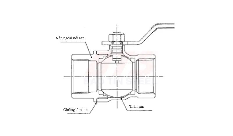
Giacomini brass safety valve manufacturing materials:
• Body: Brass UNI EN 12165 CW617N
• Membrane: EPDM
• Shaft: brass
• Separator: UNI Brass EN 12164 CW617N
• Gasket: Vegetable fiber
• Spring: Steel
• Spring propeller: Brass UNI EN 12164 CW617N
• Bonnet: Brass UNI EN 12165 CW617N
• Knob: POM

Application of Giacomini . brass safety valve
Brass safety valves are used in:
- Hot water heating systems have a closed expansion vessel, to ensure that the pressure of the fluid in the heater does not exceed the project limits. When the thrust of the pressurized liquid activates the return spring on the shutter, the valve discharges a quantity of liquid to prevent exceeding a specified pressure level, then closes within the allowable closing range.
- They can also be used to drain cold water in water systems.
And most of them are factory calibrated and cannot change the drain pressure value.
Notes when installing Giacomini Brass safety valve R140/R140M . series
To install the Giacomini brass safety valve correctly and ensure optimal operation, please note the following:
- Before installing any Giacomini brass safety valve, the system technician must calibrate it correctly per applicable regulations.
- Safety valves must be installed in the highest part of the heater or on the distribution pipe, no more than 1m from the heater.
- They must be visible and easy to inspect.
- The piping connecting the safety valve to the generator shall be free of any obstructions and shall have a diameter not less than the diameter of the valve itself.
- The relief valve drain must be visible and directed into a pipe no less than the diameter of the valve.
Instructions for the use, maintenance, installation, and operation of the valve
Note: The instructions for use below may not describe any particular valve in detail. To use each type of valve safely and effectively. Please read and double-check the user manual for each product, which is included with each package.
Instructions for preservation in transport and storage
For products shipped from Bao Tin Steel Co., Ltd. We guarantee valve products are in original, unworn condition.
However, the strength of the carton box may decrease due to moisture, etc. and the packaging may be damaged. Be very careful when shipping products in carton boxes.
When moving the valve, absolutely do not move by holding or holding the operating parts of the valve. As the valve operating part may fall off and the product may fall resulting in damage.
Do not drop, vibrate or place heavy objects on the valve during transportation or storage.
Store the valve in a well-ventilated room with little dust and moisture.
To maintain product quality, Bao Tin Steel can implement various protective measures:
- Lubricating with lubricating oil
- Wrapped in a plastic bag
Before shipping to prevent rust and dust.
Please keep this condition until the valve is installed into the piping system.
When storing ball valves, keep the ball valve parts in the “fully open” state. Avoid half-opening the ball, as that may cause the seals to be deformed or damaged.
Safety measures for pipe connection
Measures before installing the valve
- Take care to ensure enough space for the connection to the product’s piping when considering operation, maintenance, inspection, and repair.
- Be careful not to put undue pressure on the valve and, if necessary, install additional pipe supports, etc.
- If the pipe expands or contracts due to temperature changes, take measures to absorb the expansion and contraction.
- Do not remove the dust cover attached to the product until just before installing the piping. Particular attention should be paid to anti-rust and anti-dust measures for products not treated with oil. In addition, a check valve may have an additional gasket fixed to the valve body. Be sure to remove these protective measures (dust cap and gasket) when installing them into the pipeline.
- Depending on valve specifications, desiccant (rust prevention) such as silica gel may be used for the valve. Be sure to remove this desiccant (anti-corrosion agent) before installing it into the pipeline.
- Before connecting the product, remove the cutting oil, workpiece, foreign matter, etc. from the connection and inside the pipe. At the same time, thoroughly clean the inner and outer surfaces of the valve.
- Also, make sure that there are no harmful scratches on the joints (flanges, threads, welds, etc.).
Measures during and after valve installation
- For products with restricted flow direction (check valve, …), note the direction of the arrow indicated on the valve body before mounting. So that it is in the same direction as the desired flow.
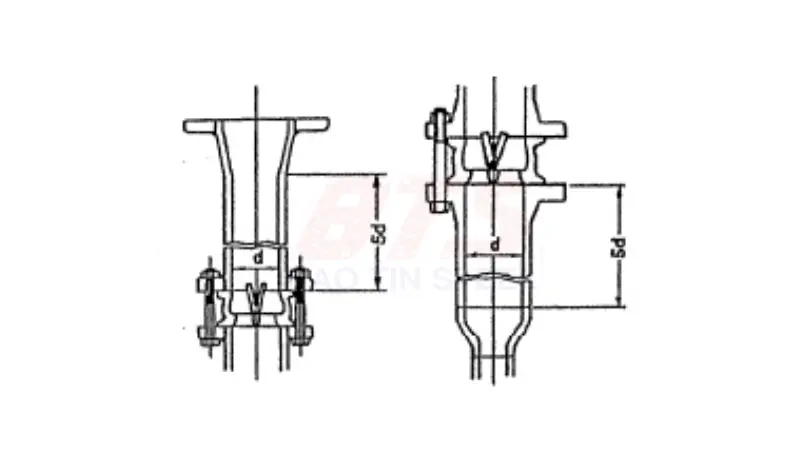
- If the front and rear pipelines of the Check valve are used, a reducer is used. Please note, the check valve must be installed at a distance of 5 times or more from the collector. To ensure that the valve works properly and is not affected by unstable flow, eddy currents form after the fitting.
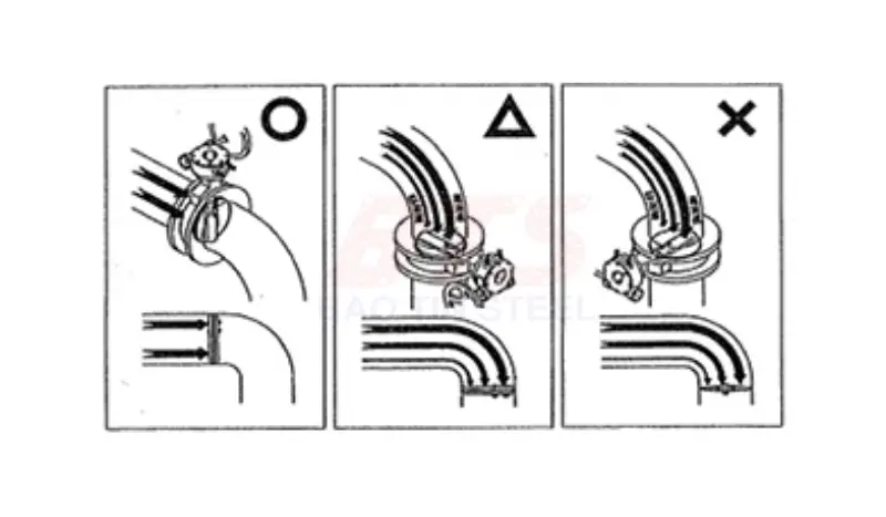
- When installing butterfly valves or butterfly check valves near welding fittings, threaded fittings, etc. Install the accessory as far upstream as possible. If installed downstream, install in the direction of the same flow rate on the left and right sides of the valve body.
- Gently open the relief valve and butterfly valve before opening the pipeline. If the pipeline is operated with the valve fully closed; the valve may no longer open. Or if force is used to try to open it, it can damage the valve disc, the suspension system (elastic parts, shock absorbers such as springs, …) of the valve or valve seat.
Valve User Manual
How to install threaded connection valves
- When threading pipes, use the thread standard suitable for the valve product used.
- For the sealing material of the threaded part (duct tape, …), use a material suitable for the working fluid, temperature, etc. Also, make sure that sealing material does not enter the valve.
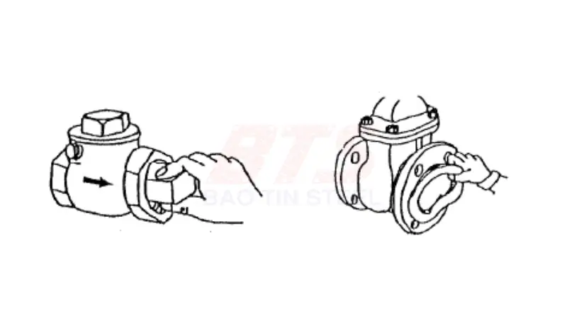
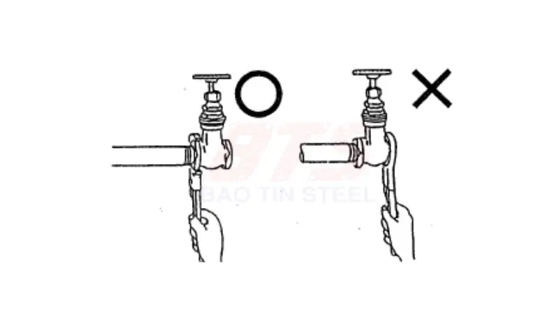
- Do not use a wrench on the product to work with pipes.
- When connecting the product to the pipe, use a suitable tool such as a wrench at the end of the connection on the side closest to the pipe as shown in the figure.
- The valve will be damaged due to the pipe ends being bumped when screwed too tight. Please turn gently, just enough to run the thread in the valve.

- For threaded ball valves, do not apply force in the (counterclockwise) direction. This will loosen the bond between the body and the cap.
=> See also the instructions for use that are packaged with each product.
Installation instructions for flanged valves
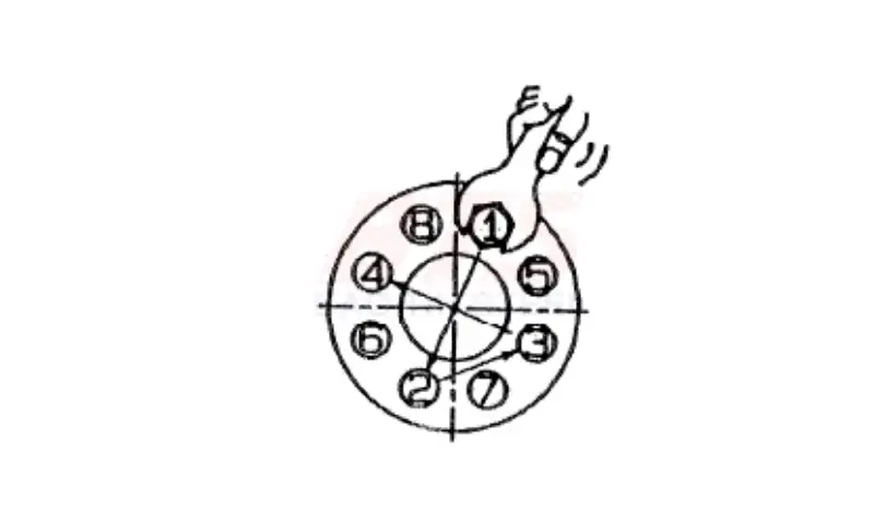
- Gradually tighten the bolts with an equal force so that the bolts on the diagonal are not tightened unevenly according to the procedure illustrated in the figure. Tighten the bolts at least twice.
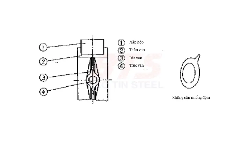
- Use washers that meet the conditions of use and do not protrude on the inside diameter side of the connector face.
- Do not use gaskets for butterfly valves when the sealing ring is integrated with the rubber plate.
- When fitting flanged valves with the outside surface lined or coated. Use beveled flat washers or the like to avoid damage to the lining surface when tightening bolts.

=> See also the instructions for use that are packaged with each product.
Be careful when using, operating
Notes on valve maintenance
After installing the pipeline, make sure to fully open the valves of the pipeline. And remove foreign matter inside the pipe by flushing (cleaning the inside of the pipe). Never open or close the valve during this flush.
The packing pressure may be reduced due to stress relaxation. Occurs due to the nature of the packaging during transportation, storage, fluid flow, and operation. Be sure to re-tighten the washer before use. If the leak continues during use and does not stop even after re-tightening. Do a daily check and re-tighten it as soon as possible. When tightening, tighten the bolt evenly.

When replacing the sealing ring, avoid a dangerous situation by releasing the pressure inside the valve.
When attaching the hot/cold insulation cover to the valve, ensure the sealing ring can be tightened and the leak can be checked.
If the valve is used at high temperatures, re-tighten the bolts and joints (hot bolt) after the temperature rises to operate temperature.
Never loosen any bolts or nuts during operation.
Do not remove the actuator from the valve under pressure.
Notes on valve operation
When opening and closing the valve, pay attention to:
- Sound of liquid passing
- Operating feeling
- Movement of the valve body.
Also, check for any harmful vibrations or abnormal sounds and ensure that the valve operates smoothly.
When operating the valve, if there is a pressure gauge or flow meter nearby, keep an eye on the device regularly.
If the valve is equipped with a bypass valve. Before operating the main valve, preheat the main line by:
- Let the liquid pass through the bypass valve។
- Equalize the pressure between the upstream and downstream sides of the main valve, etc.
When a liquid with a high temperature such as steam is allowed to pass through. It takes time for the valve to reach a steady state with temperature. The temperature is as uniform as possible so as not to cause adverse effects such as:
- Thermal deformation
- Uneven dilation
- Gas stagnation, air release, etc.
If the fluid is liquid, open and close the valve slowly so as not to cause a water hammer.
If the fluid is a liquid in a closed line (the pipe is cut off by a shut-off valve, etc.). The pressure in a sealed fluid may increase abnormally due to an increase in the temperature of the liquid or of the medium. Please take appropriate measures such as:
- Install more pressure relief valve
Following valve operating procedures does not create a closed pipeline.
It is recommended to periodically change the open/closed state of the valve. To avoid deterioration of serviceability or sticking of moving parts of the valve.
Product Maintenance Manual
o, ensure that the product can be used safely for a long time. Conduct systematic daily and periodic checks. To detect abnormalities early and take appropriate measures when necessary. For details, please check the user manual that came with the product.
In addition, the product, even if used correctly, has a certain lifespan. This depends on the conditions of use and the characteristics of each product. It is necessary to replace components, replace products or change to suitable products.