
 Tiếng Việt
 ភាសាខ្មែរ
Aluminum flanges are used to connect pipes, valves, accessories, and special items such as filters and pressure vessels. So do you know anything about this type of flange? If not, follow the article below by Bao Tin Steel.
What is an aluminum flange?
“The aluminum flange is a flange made of aluminum material. This is also a type of flange widely used in civil water pipeline systems, fire protection systems, etc.

-> Aluminum is a lightweight, durable, corrosion-resistant, and easily machined metal widely used in industrial applications.
Technical specifications of aluminum flanges
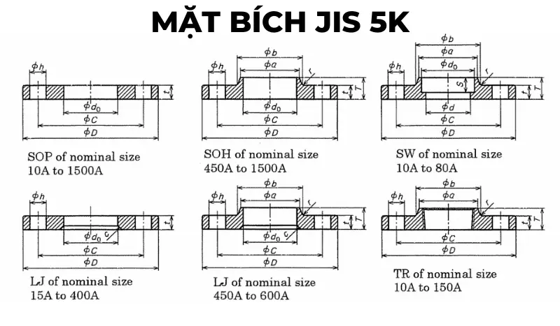
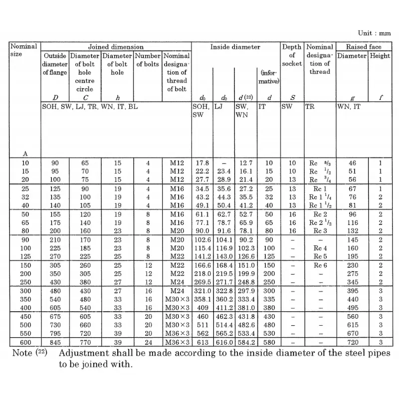
JIS 5K flange standard specifications

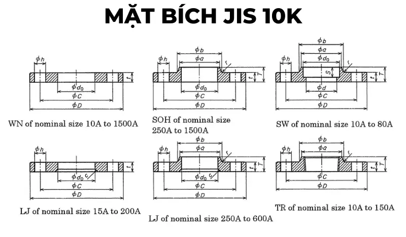
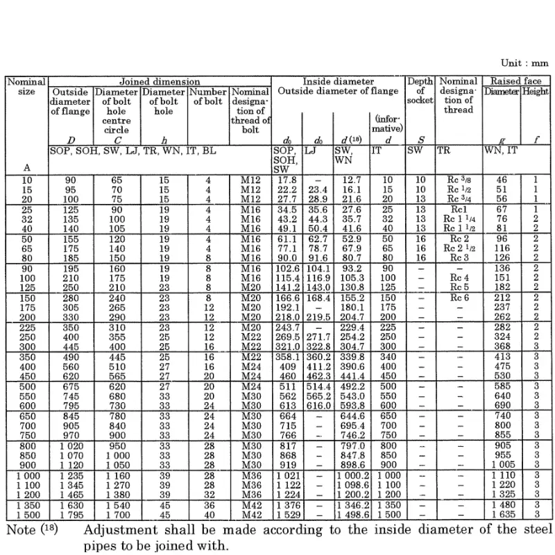
JIS 10K flange standard specifications
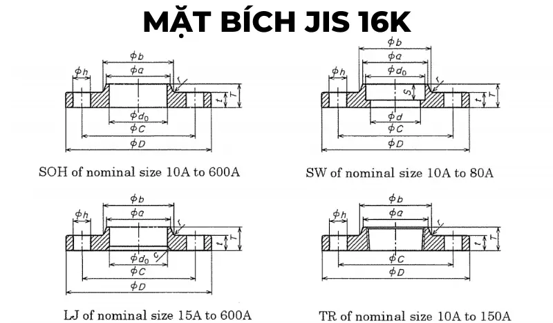
JIS 16K flange standard specifications
JIS 20K flange standard specifications


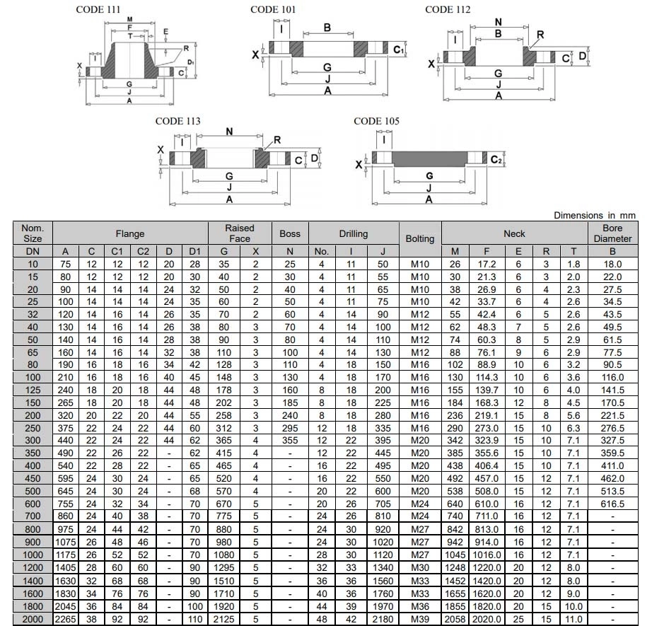
Flange specifications manufactured according to DIN standards
DIN 2576 – PN6 flange standard specifications
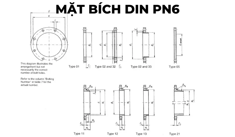
DIN PN6 Flange Technical Data Sheet
| DN | Link Details | Outer diameter of weld neck | Diameter hole | Flange thickness | Beveled face | Measure connector thickness | Welding face diameter | Length | Welding neck diameter | Connector bevel angle | Neck thicknessn | |||||||||||
|---|---|---|---|---|---|---|---|---|---|---|---|---|---|---|---|---|---|---|---|---|---|---|
| Outer diameter | Bolt circle diameter | Bolt hole diameter | Bolt | |||||||||||||||||||
| D | K | L | Quantity | Size | A | B1 | B2 | C1 | C2 C3 |
C4 | E | F | G max | H1 | H2 | H3 | N1 | N2 | N3 | R1 | S | |
| Flange Type | ||||||||||||||||||||||
| 01, 02, 05, 11, 12, 13, 21 | 11 21b |
01 12 32 |
2 | 01 02 |
11 12 13 21 |
5 | 2 | 32 | 5 | 12 13 |
11 | 11 | 11 | 12 13 |
21 | 11 12 13 21 |
11 | |||||
| 10 | 75 | 50 | 11 | 4 | M10 | 17,2 | 18 | 21 | 12 | 12 | 12 | 3 | 10 | – | 20 | 28 | 6 | 26 | 25 | 20 | 4 | 1,8 |
| 15 | 80 | 55 | 11 | 4 | M10 | 21,3 | 22 | 25 | 12 | 12 | 12 | 3 | 10 | – | 20 | 30 | 6 | 30 | 30 | 26 | 4 | 2 |
| 20 | 90 | 65 | 11 | 4 | M10 | 26,9 | 27,5 | 31 | 14 | 14 | 14 | 4 | 10 | – | 24 | 32 | 6 | 38 | 40 | 34 | 4 | 2,3 |
| 25 | 100 | 75 | 11 | 4 | M10 | 33,7 | 34,5 | 38 | 14 | 14 | 14 | 4 | 10 | – | 24 | 35 | 6 | 42 | 50 | 44 | 4 | 2,6 |
| 32 | 120 | 90 | 14 | 4 | M12 | 42,4 | 43,5 | 46 | 16 | 14 | 14 | 5 | 10 | – | 26 | 35 | 6 | 55 | 60 | 54 | 6 | 2,6 |
| 40 | 130 | 100 | 14 | 4 | M12 | 48,3 | 49,5 | 53 | 16 | 14 | 14 | 5 | 10 | – | 26 | 38 | 7 | 62 | 70 | 64 | 6 | 2,6 |
| 50 | 140 | 110 | 14 | 4 | M12 | 60,3 | 61,5 | 65 | 16 | 14 | 14 | 5 | 12 | – | 28 | 38 | 8 | 74 | 80 | 74 | 6 | 2,9 |
| 65 | 160 | 130 | 14 | 4 | M12 | 76,1 | 77,5 | 81 | 16 | 14 | 14 | 6 | 12 | 55 | 32 | 38 | 9 | 88 | 100 | 94 | 6 | 2,9 |
| 80 | 190 | 150 | 18 | 4 | M16 | 88,9 | 90,5 | 94 | 18 | 16 | 16 | 6 | 12 | 70 | 34 | 42 | 10 | 102 | 110 | 110 | 8 | 3,2 |
| 100 | 210 | 170 | 18 | 4 | M16 | 114,3 | 116 | 120 | 18 | 16 | 16 | 6 | 14 | 90 | 40 | 45 | 10 | 130 | 130 | 130 | 8 | 3,6 |
| 125 | 240 | 200 | 18 | 8 | M16 | 139,7 | 141,5 | 145 | 20 | 18 | 18 | 6 | 14 | 115 | 44 | 48 | 10 | 155 | 160 | 160 | 8 | 4 |
| 150 | 265 | 225 | 18 | 8 | M16 | 168,3 | 170,5 | 174 | 20 | 18 | 18 | 6 | 14 | 140 | 44 | 48 | 12 | 184 | 185 | 182 | 10 | 4,5 |
| 200 | 320 | 280 | 18 | 8 | M16 | 219,1 | 221,5 | 226 | 22 | 20 | 20 | 6 | 16 | 190 | 44 | 55 | 15 | 236 | 240 | 238 | 10 | 6,3 |
| 250 | 375 | 335 | 18 | 12 | M16 | 273 | 276,5 | 281 | 24 | 22 | 22 | 8 | 18 | 235 | 44 | 60 | 15 | 290 | 295 | 284 | 12 | 6,3 |
| 300 | 440 | 395 | 22 | 12 | M20 | 323,9 | 327,5 | 333 | 24 | 22 | 22 | 8 | 18 | 285 | 44 | 62 | 15 | 342 | 355 | 342 | 12 | 7,1 |
| 350 | 490 | 445 | 22 | 12 | M20 | 355,6 | 359,5 | 365 | 26 | 22 | 22 | 8 | 18 | 330 | – | 62 | 15 | 385 | – | 392 | 12 | 7,1 |
| 400 | 540 | 495 | 22 | 16 | M20 | 406,4 | 411 | 416 | 28 | 22 | 22 | 8 | 20 | 380 | – | 65 | 15 | 438 | – | 442 | 12 | 7,1 |
| 450 | 595 | 550 | 22 | 16 | M20 | 457 | 462 | 467 | 30 | 22 | 24 | 8 | 20 | 425 | – | 65 | 15 | 492 | – | 494 | 12 | 7,1 |
DIN 2576 – PN10 flange standard specifications
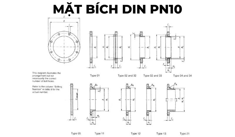
DIN PN10 Flange Technical Data Sheet
| DN | Link Details | Outer diameter of weld neck | Diameter hole | Flange thickness | Beveled face | Measure connector thickness | Welding face diameter | Length | Welding neck diameter | Connector bevel angle | Welding neck thickness | |||||||||||||
|---|---|---|---|---|---|---|---|---|---|---|---|---|---|---|---|---|---|---|---|---|---|---|---|---|
| Outer diameter | Bolt circle diameter | Bolt hole diameter | Bolt | |||||||||||||||||||||
| D | K | L | Quantity | Size | A | B1 | B2 | B3 | C1 | C2 | C3 | C4 | E | F | G max | H1 | H2 | H3 | N1 | N2 | N3 | R1 | S | |
| Flange Type | ||||||||||||||||||||||||
| 01, 02, 04, 05, 11, 12, 13, 21 | 11 21 34 |
01 12 32 |
2 | 4 | 01 02 04 |
11 12 13 |
21 | 5 | 02 04 |
32 34 |
5 | 12 13 |
11 14 |
11 14 |
11 14 |
12 13 |
21 | 11 12 13 21 |
11 34 |
|||||
| 10 to 40 | Use pressure level PN40 | |||||||||||||||||||||||
| 50 to 150 | Use pressure level PN16 | |||||||||||||||||||||||
| 200 | 340 | 295 | 22 | 8 | M20 | 219,1 | 221,5 | 226 | 240 | 24 | 24 | 24 | 24 | 6 | 20 | 190 | 44 | 62 | 16 | 234 | 246 | 246 | 10 | 6,3 |
| 250 | 395 | 350 | 22 | 12 | M20 | 273 | 276,5 | 281 | 294 | 26 | 26 | 26 | 26 | 8 | 22 | 235 | 46 | 68 | 16 | 292 | 298 | 298 | 12 | 6,3 |
| 300 | 445 | 400 | 22 | 12 | M20 | 323,9 | 327,5 | 333 | 348 | 26 | 26 | 26 | 26 | 8 | 22 | 285 | 46 | 68 | 16 | 342 | 350 | 348 | 12 | 7,1 |
| 350 | 505 | 460 | 22 | 16 | M20 | 355,6 | 359,5 | 365 | 400 | 28 | 26 | 26 | 26 | 8 | 22 | 330 | 53 | 68 | 16 | 385 | 400 | 408 | 12 | 7,1 |
| 400 | 565 | 515 | 26 | 16 | M24 | 406,4 | 411 | 416 | 450 | 32 | 26 | 26 | 26 | 8 | 24 | 380 | 57 | 72 | 16 | 440 | 456 | 456 | 12 | 7,1 |
| 450 | 615 | 565 | 26 | 20 | M24 | 457 | 462 | 467 | 498 | 36 | 28 | 28 | 28 | 8 | 24 | 425 | 63 | 72 | 16 | 488 | 502 | 502 | 12 | 7,1 |
| 500 | 670 | 620 | 26 | 20 | M24 | 508 | 513,5 | 519 | 550 | 38 | 28 | 28 | 28 | 8 | 26 | 475 | 67 | 75 | 16 | 542 | 559 | 559 | 12 | 7,1 |
| 600 | 780 | 725 | 30 | 20 | M27 | 610 | 616,5 | 622 | 650 | 42 | 28 | 34 | 34 | 8 | 26 | 575 | 75 | 80 | 18 | 642 | 658 | 658 | 12 | 7,1 |
| 700 | 895 | 840 | 30 | 24 | M27 | 711 | 30 | 34 | 38 | 670 | 80 | 18 | 746 | 772 | 12 | 8 | ||||||||
| 800 | 1015 | 950 | 33 | 24 | M30 | 813 | 32 | 36 | 42 | 770 | 90 | 18 | 850 | 876 | 12 | 8 | ||||||||
| 900 | 1115 | 1050 | 33 | 28 | M30 | 914 | 34 | 38 | 46 | 860 | 95 | 20 | 950 | 976 | 12 | 10 | ||||||||
| 1000 | 1230 | 1160 | 36 | 28 | M33 | 1016 | 34 | 38 | 52 | 960 | 95 | 20 | 1052 | 1080 | 16 | 10 | ||||||||
| 1200 | 1455 | 1380 | 39 | 32 | M36 | 1219 | 38 | 44 | 60 | 1160 | 115 | 25 | 1256 | 1292 | 16 | 11 | ||||||||
| 1400 | 1675 | 1590 | 42 | 36 | M39 | 1422 | 42 | 48 | 120 | 25 | 1460 | 1496 | 16 | 12 | ||||||||||
| 1600 | 1915 | 1820 | 48 | 40 | M45 | 1626 | 46 | 52 | 130 | 25 | 1666 | 1712 | 16 | 14 | ||||||||||
| 1800 | 2115 | 2020 | 48 | 44 | M45 | 1829 | 50 | 56 | 140 | 30 | 1868 | 1910 | 16 | 15 | ||||||||||
| 2000 | 2325 | 2230 | 48 | 48 | M45 | 2032 | 54 | 60 | 150 | 30 | 2072 | 2120 | 16 | 16 | ||||||||||
| 2200 | 2550 | 2440 | 56 | 52 | M52 | 2235 | 58 | 160 | 35 | 2275 | 18 | 18 | ||||||||||||
| 2400 | 2760 | 2650 | 56 | 56 | M52 | 2438 | 62 | 170 | 35 | 2478 | 18 | 20 | ||||||||||||
| 2600 | 2960 | 2850 | 56 | 60 | M52 | 2620 | 66 | 180 | 40 | 2680 | 18 | 22 | ||||||||||||
| 2800 | 3180 | 3070 | 56 | 64 | M52 | 2820 | 70 | 190 | 40 | 2882 | 18 | 22 | ||||||||||||
| 3000 | 3405 | 3290 | 62 | 68 | M56 | 3020 | 75 | 200 | 45 | 3085 | 18 | 24 | ||||||||||||
DIN 2544 – PN16 flange standard specifications

DIN PN16 Flange Technical Data Sheet
| DN | Link Details | Outer diameter of weld neck | Diameter hole | Flange thickness | Beveled face | Measure connector thickness | Welding face diameter | Length | Welding neck diameter | Connector bevel angle | Welding neck thickness | |||||||||||||
|---|---|---|---|---|---|---|---|---|---|---|---|---|---|---|---|---|---|---|---|---|---|---|---|---|
| Outer diameter | Bolt circle diameter | Bolt hole diameter | Bolt | |||||||||||||||||||||
| D | K | L | Quantity | Size | A | B1 | B2 | B3 | C1 | C2 | C3 | C4 | E | F | G max | H1 | H2 | H3 | N1 | N2 | N3 | R1 | S | |
| Flange Type | ||||||||||||||||||||||||
| 01, 02, 04, 05, 11, 12, 13, 21 | 11 21 34 |
01 12 32 |
2 | 4 | 01 02 04 |
11 12 13 |
21 | 5 | 02 04 |
32 34 |
5 | 12 13 |
11 14 |
11 14 |
11 14 |
12 13 |
21 | 11 12 13 21 |
11 34 |
|||||
| 10 to 40 | Sử dụng mặt bích cấp áp suất PN40 | |||||||||||||||||||||||
| 50 | 165 | 125 | 18 | 4 | M16 | 60,3 | 61,5 | 65 | 77 | 19 | 18 | 18 | 18 | 5 | 16 | 28 | 45 | 8 | 74 | 84 | 84 | 5 | 2,9 | |
| 65 | 185 | 145 | 18 | 8 | M16 | 76,1 | 77,5 | 81 | 96 | 20 | 18 | 18 | 18 | 6 | 16 | 55 | 32 | 45 | 10 | 92 | 104 | 104 | 6 | 2,9 |
| 80 | 200 | 160 | 18 | 8 | M16 | 88,9 | 90,5 | 94 | 108 | 20 | 20 | 20 | 20 | 6 | 16 | 70 | 34 | 50 | 10 | 105 | 118 | 120 | 6 | 3,2 |
| 100 | 220 | 180 | 18 | 8 | M16 | 114,3 | 116 | 120 | 134 | 22 | 20 | 20 | 20 | 6 | 18 | 90 | 40 | 52 | 12 | 131 | 140 | 140 | 8 | 3,6 |
| 125 | 250 | 210 | 18 | 8 | M16 | 139,7 | 141,5 | 145 | 162 | 22 | 22 | 22 | 22 | 6 | 18 | 115 | 44 | 55 | 12 | 156 | 168 | 170 | 8 | 4 |
| 150 | 285 | 240 | 22 | 8 | M20 | 168,3 | 170,5 | 174 | 188 | 24 | 22 | 22 | 22 | 6 | 20 | 140 | 44 | 55 | 12 | 184 | 195 | 190 | 10 | 4,5 |
| 200 | 340 | 295 | 22 | 12 | M20 | 219,1 | 221,5 | 226 | 240 | 26 | 24 | 24 | 24 | 6 | 20 | 190 | 44 | 62 | 16 | 235 | 246 | 246 | 10 | 6,3 |
| 250 | 405 | 355 | 26 | 12 | M24 | 273 | 276,5 | 281 | 294 | 29 | 26 | 26 | 26 | 8 | 22 | 235 | 46 | 70 | 16 | 292 | 298 | 296 | 12 | 6,3 |
| 300 | 460 | 410 | 26 | 12 | M24 | 323,9 | 327,5 | 33 | 348 | 32 | 28 | 28 | 28 | 8 | 24 | 285 | 46 | 78 | 16 | 344 | 350 | 350 | 12 | 7,1 |
| 350 | 520 | 470 | 26 | 16 | M24 | 355,6 | 359 | 365 | 400 | 35 | 30 | 30 | 30 | 8 | 26 | 330 | 57 | 82 | 16 | 390 | 400 | 410 | 12 | 8 |
| 400 | 580 | 525 | 30 | 16 | M27 | 406,4 | 411 | 416 | 454 | 38 | 32 | 32 | 32 | 8 | 28 | 380 | 63 | 85 | 16 | 445 | 456 | 458 | 12 | 8 |
| 450 | 640 | 585 | 30 | 20 | M27 | 457 | 462 | 467 | 500 | 42 | 40 | 40 | 40 | 8 | 30 | 425 | 68 | 87 | 16 | 490 | 502 | 516 | 12 | 8 |
| 500 | 715 | 650 | 33 | 20 | M30 | 508 | 513,5 | 510 | 556 | 46 | 44 | 44 | 44 | 8 | 32 | 475 | 73 | 90 | 16 | 548 | 559 | 576 | 12 | 8 |
| 600 | 840 | 770 | 36 | 20 | M33 | 610 | 616,5 | 622 | 660 | 52 | 54 | 54 | 54 | 8 | 32 | 575 | 83 | 95 | 18 | 652 | 658 | 690 | 12 | 8,8 |
| 700 | 910 | 840 | 36 | 24 | M33 | 711 | 36 | 42 | 48 | 670 | 83 | 100 | 18 | 755 | 760 | 760 | 12 | 8,8 | ||||||
| 800 | 1025 | 950 | 39 | 24 | M36 | 813 | 38 | 42 | 52 | 770 | 90 | 105 | 20 | 855 | 864 | 862 | 12 | 10 | ||||||
| 900 | 1125 | 1050 | 39 | 28 | M36 | 914 | 40 | 44 | 58 | 860 | 94 | 110 | 20 | 955 | 968 | 962 | 12 | 10 | ||||||
| 1000 | 1255 | 1170 | 42 | 28 | M39 | 1016 | 42 | 46 | 64 | 960 | 100 | 120 | 22 | 1058 | 1072 | 1070 | 16 | 10 | ||||||
| 1200 | 1485 | 1390 | 48 | 32 | M45 | 1219 | 48 | 52 | 76 | 1160 | 130 | 30 | 1262 | 1282 | 16 | 12,5 | ||||||||
| 1400 | 1685 | 1590 | 48 | 36 | M45 | 1422 | 52 | 58 | 1346 | 145 | 30 | 1465 | 1482 | 16 | 14,2 | |||||||||
| 1600 | 1930 | 1820 | 56 | 40 | M52 | 1626 | 58 | 64 | 1546 | 160 | 35 | 1668 | 1696 | 16 | 16 | |||||||||
| 1800 | 2130 | 2020 | 56 | 44 | M52 | 1829 | 62 | 68 | 1746 | 170 | 35 | 1870 | 1896 | 16 | 17,5 | |||||||||
| 2000 | 2345 | 2230 | 62 | 48 | M56 | 2032 | 66 | 70 | 1950 | 180 | 40 | 2072 | 2100 | 16 | 20 | |||||||||
DIN 2544 – PN25 flange standard specifications
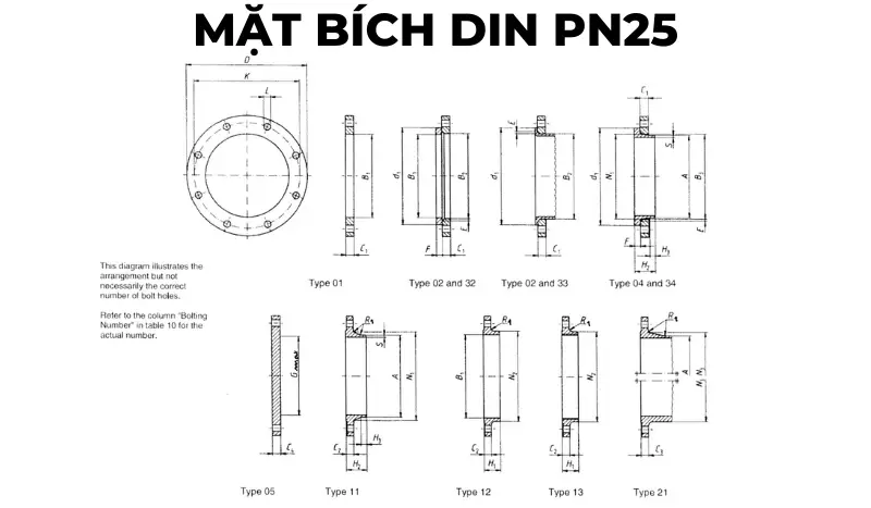
DIN PN25 Flange Technical Data Sheet
| DN | Link Details | Outer diameter of weld neck | Diameter hole | Flange thickness | Beveled face | Measure connector thickness | Welding face diameter | Length | Welding neck diameter | Connector bevel angle | Welding neck thickness | |||||||||||||
|---|---|---|---|---|---|---|---|---|---|---|---|---|---|---|---|---|---|---|---|---|---|---|---|---|
| Outer diameter | Bolt circle diameter | Bolt hole diameter | Bolt | |||||||||||||||||||||
| D | K | L | Quantity | Size | A | B1 | B2 | B3 | C1 | C2 | C3 | C4 | E | F | G max | H1 | H2 | H3 | N1 | N2 | N3 | R1 | S | |
| Flange Type | ||||||||||||||||||||||||
| 01, 02, 04, 05, 11, 12, 13, 21 | 11 21 34 |
01 12 32 |
2 | 4 | 01 02 04 |
11 12 13 |
21 | 5 | 02 04 |
32 34 |
5 | 12 13 |
11 14 |
11 14 |
11 14 |
12 13 |
21 | 11 12 13 21 |
11 34 |
|||||
| 10 to 150 | Use flange type with pressure class PN40 | |||||||||||||||||||||||
| 200 | 360 | 310 | 26 | 12 | M24 | 219,1 | 221,5 | 226 | 250 | 32 | 30 | 30 | 30 | 6 | 26 | 190 | 52 | 80 | 16 | 244 | 256 | 252 | 10 | 6,3 |
| 250 | 425 | 370 | 30 | 12 | M27 | 273 | 276,5 | 281 | 302 | 35 | 32 | 32 | 32 | 8 | 26 | 235 | 60 | 88 | 18 | 298 | 310 | 304 | 12 | 7,1 |
| 300 | 485 | 430 | 30 | 16 | M27 | 323,9 | 327,5 | 333 | 356 | 38 | 34 | 34 | 34 | 8 | 28 | 285 | 67 | 92 | 18 | 352 | 364 | 364 | 12 | 8 |
| 350 | 555 | 490 | 33 | 16 | M30 | 355,6 | 359,5 | 365 | 408 | 42 | 38 | 38 | 38 | 8 | 32 | 332 | 72 | 100 | 20 | 398 | 418 | 418 | 12 | 8 |
| 400 | 620 | 550 | 36 | 16 | M33 | 406,4 | 411 | 416 | 462 | 46 | 40 | 40 | 40 | 8 | 34 | 380 | 78 | 110 | 20 | 452 | 472 | 472 | 12 | 8,8 |
| 450 | 670 | 600 | 36 | 20 | M33 | 457 | 462 | 467 | 510 | 50 | 46 | 46 | 46 | 8 | 36 | 425 | 84 | 110 | 20 | 500 | 520 | 520 | 12 | 8,8 |
| 500 | 730 | 660 | 36 | 20 | M33 | 508 | 513,5 | 519 | 568 | 56 | 48 | 48 | 48 | 8 | 38 | 475 | 90 | 125 | 20 | 558 | 580 | 580 | 12 | 10 |
| 600 | 845 | 770 | 39 | 20 | M36 | 610 | 616,5 | 622 | 670 | 68 | 58 | 58 | 58 | 8 | 40 | 575 | 100 | 125 | 20 | 660 | 684 | 684 | 12 | 11 |
| 700 | 960 | 875 | 42 | 24 | M39 | 711 | 46 | 50 | 125 | 20 | 760 | 780 | 12 | 12,5 | ||||||||||
| 800 | 1085 | 990 | 48 | 24 | M45 | 813 | 50 | 54 | 135 | 22 | 864 | 882 | 12 | 14,2 | ||||||||||
| 900 | 1185 | 1090 | 48 | 28 | M45 | 914 | 54 | 58 | 145 | 24 | 968 | 982 | 12 | 16 | ||||||||||
| 1000 | 1320 | 1210 | 56 | 28 | M52 | 1016 | 58 | 62 | 155 | 24 | 1070 | 1086 | 16 | 17,5 | ||||||||||
| 1200 | 1530 | 1420 | 56 | 32 | M52 | 1219 | 70 | 1296 | 18 | |||||||||||||||
| 1400 | 1755 | 1640 | 62 | 36 | M56 | 1422 | 76 | 1508 | 18 | |||||||||||||||
| 1600 | 1975 | 1860 | 62 | 40 | M56 | 1626 | 84 | 1726 | 20 | |||||||||||||||
| 1800 | 2195 | 2070 | 70 | 44 | M64 | 1829 | 90 | 1920 | 20 | |||||||||||||||
| 2000 | 2425 | 2300 | 70 | 48 | M64 | 2032 | 96 | 2150 | 20 | |||||||||||||||
DIN 2544 – PN40 flange standard specifications
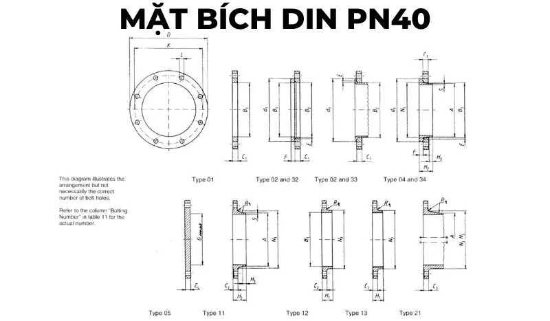
DIN PN40 Flange Technical Data Sheet
| DN | Link Details | Outer diameter of weld neck | Diameter hole | Flange thickness | Beveled face | Measure connector thickness | Welding face diameter | Length | Welding neck diameter | Connector bevel angle | Welding neck thickness | |||||||||||||
|---|---|---|---|---|---|---|---|---|---|---|---|---|---|---|---|---|---|---|---|---|---|---|---|---|
| Outer diameter | Bolt circle diameter | Bolt hole diameter | Bolt | |||||||||||||||||||||
| D | K | L | Quantity | Size | A | B1 | B2 | B3 | C1 | C2 | C3 | C4 | E | F | G max | H1 | H2 | H3 | N1 | N2 | N3 | R1 | S | |
| Flange Type | ||||||||||||||||||||||||
| 01, 02, 04, 05, 11, 12, 13, 21 | 11 21 34 |
01 12 32 |
2 | 4 | 01 02 04 |
11 12 13 |
21 | 5 | 02 04 |
32 34 |
5 | 12 13 |
11 14 |
11 14 |
11 14 |
12 13 |
21 | 11 12 13 21 |
11 34 |
|||||
| 10 | 90 | 60 | 14 | 4 | M12 | 17,2 | 18 | 21 | 31 | 14 | 16 | 16 | 16 | 3 | 12 | 22 | 35 | 6 | 28 | 30 | 28 | 4 | 1,8 | |
| 15 | 95 | 65 | 14 | 4 | M12 | 21,3 | 22 | 25 | 35 | 14 | 16 | 16 | 16 | 3 | 12 | 22 | 38 | 6 | 32 | 35 | 32 | 4 | 2 | |
| 20 | 105 | 75 | 14 | 4 | M12 | 26,9 | 27,5 | 31 | 42 | 16 | 18 | 18 | 18 | 4 | 14 | 26 | 40 | 6 | 40 | 45 | 40 | 4 | 2,3 | |
| 25 | 115 | 85 | 14 | 4 | M12 | 33,7 | 34,5 | 38 | 49 | 16 | 18 | 18 | 18 | 4 | 14 | 28 | 40 | 6 | 46 | 52 | 50 | 4 | 2,6 | |
| 32 | 140 | 100 | 18 | 4 | M16 | 42,4 | 43,5 | 47 | 59 | 18 | 18 | 18 | 18 | 5 | 14 | 30 | 42 | 6 | 56 | 60 | 60 | 6 | 2,6 | |
| 40 | 150 | 110 | 18 | 4 | M16 | 48,3 | 49,5 | 53 | 67 | 18 | 18 | 18 | 18 | 5 | 14 | 32 | 45 | 7 | 64 | 70 | 70 | 6 | 2,6 | |
| 50 | 165 | 125 | 18 | 4 | M16 | 60,3 | 61,5 | 65 | 77 | 20 | 20 | 20 | 20 | 5 | 16 | 34 | 48 | 8 | 75 | 84 | 84 | 6 | 2,9 | |
| 65 | 185 | 145 | 18 | 8 | M16 | 76,1 | 77,5 | 81 | 96 | 22 | 22 | 22 | 22 | 6 | 16 | 55 | 38 | 52 | 10 | 90 | 104 | 104 | 6 | 2,9 |
| 80 | 200 | 160 | 18 | 8 | M16 | 88,9 | 90,5 | 94 | 114 | 24 | 24 | 24 | 24 | 6 | 18 | 70 | 40 | 58 | 12 | 105 | 118 | 120 | 8 | 3,2 |
| 100 | 235 | 190 | 22 | 8 | M20 | 114,3 | 116 | 120 | 138 | 26 | 24 | 24 | 24 | 6 | 20 | 90 | 44 | 65 | 12 | 134 | 145 | 142 | 8 | 3,6 |
| 125 | 270 | 220 | 26 | 8 | M24 | 139,7 | 141,5 | 145 | 166 | 28 | 26 | 26 | 26 | 6 | 22 | 115 | 48 | 68 | 12 | 162 | 170 | 162 | 8 | 4 |
| 150 | 300 | 250 | 26 | 8 | M24 | 168,3 | 170,5 | 174 | 194 | 30 | 28 | 28 | 28 | 6 | 24 | 140 | 52 | 75 | 12 | 192 | 200 | 192 | 10 | 4,5 |
| 200 | 375 | 320 | 30 | 12 | M27 | 219,1 | 221,5 | 226 | 250 | 36 | 34 | 34 | 36 | 6 | 28 | 190 | 52 | 88 | 16 | 244 | 260 | 254 | 10 | 6,3 |
| 250 | 450 | 385 | 33 | 12 | M30 | 273 | 276,5 | 281 | 312 | 38 | 38 | 38 | 38 | 8 | 30 | 235 | 60 | 105 | 18 | 306 | 312 | 312 | 12 | 7,1 |
| 300 | 515 | 450 | 33 | 16 | M30 | 323,9 | 327,5 | 333 | 368 | 42 | 42 | 42 | 42 | 8 | 34 | 285 | 67 | 115 | 18 | 362 | 380 | 378 | 12 | 8 |
| 350 | 580 | 510 | 36 | 16 | M33 | 355,6 | 359,5 | 365 | 418 | 46 | 46 | 46 | 46 | 8 | 36 | 330 | 72 | 125 | 20 | 408 | 424 | 432 | 12 | 8,8 |
| 400 | 660 | 585 | 39 | 16 | M36 | 406,4 | 411 | 416 | 472 | 50 | 50 | 50 | 50 | 8 | 42 | 380 | 78 | 135 | 20 | 462 | 478 | 498 | 12 | 11 |
| 450 | 685 | 610 | 39 | 20 | M36 | 457 | 462 | 467 | 510 | 57 | 57 | 57 | 57 | 8 | 46 | 425 | 84 | 135 | 20 | 500 | 522 | 522 | 12 | 12,5 |
| 500 | 755 | 670 | 42 | 20 | M39 | 508 | 513,5 | 519 | 572 | 57 | 57 | 57 | 57 | 8 | 50 | 475 | 90 | 140 | 20 | 562 | 576 | 576 | 12 | 14,2 |
| 600 | 890 | 795 | 48 | 20 | M45 | 610 | 616,5 | 622 | 676 | 72 | 72 | 72 | 72 | 8 | 54 | 575 | 100 | 150 | 20 | 666 | 686 | 686 | 12 | 16 |
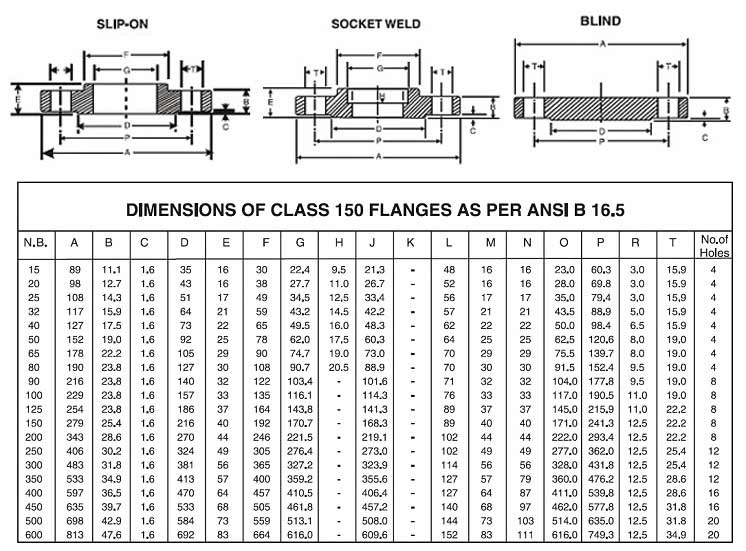
Standard specifications of flanges manufactured according to ANSI standards
ANSI 150 Series Flange Standard Specifications
ANSI 300 Series Flange Standard Specifications
 ????????????In addition to the 2 popular series 150 & 300, ANSI flanges also have other series 400, 600, 900, 1500, and 2500. You can see more in the table below (Document cited from ASME/ANSI B16.10/19 standard).
| Current | Pipe Size (inches) |
Flange outside diameter (mm) | Pipe Outer Diameter (mm) | Number of bolt holes | Bolt Hole Diameter (mm) | Bolt Circle (mm) |
|---|---|---|---|---|---|---|
| 400 Series | 1/2 | 57,2 | 21,3 | 4,0 | 15,9 | 34,9 |
| 3/4 | 85,7 | 26,7 | 4,0 | 19,1 | 69,9 | |
| 1 | 79,4 | 33,5 | 4,0 | 19,1 | 63,5 | |
| 1-1 / 4 | 120,7 | 42,2 | 4,0 | 19,1 | 54,0 | |
| 1-1 / 2 | 149,2 | 48,3 | 4,0 | 22,2 | 88,9 | |
| 2 | 139,7 | 60,5 | 8,0 | 19,1 | 127,0 | |
| 2-1 / 2 | 165,1 | 73,2 | 8,0 | 22,2 | 104,8 | |
| 3 | 196,9 | 88,9 | 8,0 | 22,2 | 136,5 | |
| 3-1 / 2 | 228,6 | 101,6 | 8,0 | 25,4 | 171,5 | |
| 4 | 254,0 | 114,3 | 8,0 | 25,4 | 181,0 | |
| 5 | 279,4 | 141,2 | 8,0 | 25,4 | 222,3 | |
| 6 | 292,1 | 168,4 | 12,0 | 25,4 | 238,1 | |
| số 8 | 381,0 | 219,2 | 12,0 | 22,2 | 330,2 | |
| 10 | 419,1 | 273,1 | 16,0 | 19,1 | 374,7 | |
| 12 | 495,3 | 323,9 | 16,0 | 15,9 | 412,8 | |
| 14 | 584,2 | 355,6 | 20,0 | 15,9 | 501,7 | |
| 16 | 622,3 | 406,4 | 20,0 | 12,7 | 546,1 | |
| 18 | 711,2 | 457,2 | 24,0 | 12,7 | 590,6 | |
| 20 | 749,3 | 508,0 | 24,0 | 9,5 | 685,8 | |
| 24 | 914,4 | 609,6 | 24,0 | 3,2 | 812,8 | |
| 600 Series | 1/2 | 57,2 | 21,3 | 4,0 | 15,9 | 34,9 |
| 3/4 | 85,7 | 26,7 | 4,0 | 19,1 | 69,9 | |
| 1 | 79,4 | 33,5 | 4,0 | 19,1 | 63,5 | |
| 1-1/4 | 120,7 | 42,2 | 4,0 | 19,1 | 54,0 | |
| 1-1/2 | 149,2 | 48,3 | 4,0 | 22,2 | 88,9 | |
| 2 | 139,7 | 60,5 | 8,0 | 19,1 | 127,0 | |
| 2-1/2 | 165,1 | 73,2 | 8,0 | 22,2 | 104,8 | |
| 3 | 196,9 | 88,9 | 8,0 | 22,2 | 136,5 | |
| 3-1/2 | 228,6 | 101,6 | 8,0 | 25,4 | 171,5 | |
| 4 | 235,0 | 114,3 | 8,0 | 25,4 | 190,5 | |
| 5 | 330,2 | 141,2 | 8,0 | 19,1 | 241,3 | |
| 6 | 355,6 | 168,4 | 12,0 | 19,1 | 266,7 | |
| 8 | 393,7 | 219,2 | 12,0 | 19,1 | 311,2 | |
| 10 | 508,0 | 273,1 | 16,0 | 15,9 | 431,8 | |
| 12 | 558,8 | 323,9 | 20,0 | 15,9 | 476,3 | |
| 14 | 565,2 | 355,6 | 20,0 | 12,7 | 489,0 | |
| 16 | 685,8 | 406,4 | 20,0 | 9,5 | 565,2 | |
| 18 | 730,3 | 457,2 | 20,0 | 6,4 | 616,0 | |
| 20 | 812,8 | 508,0 | 24,0 | 6,4 | 698,5 | |
| 24 | 939,8 | 609,6 | 24,0 | 50,8 | 838,2 | |
| 900 Series | 1/2 | 82,6 | 21,3 | 4,0 | 22,2 | 69,9 |
| 3/4 | 123,8 | 26,7 | 4,0 | 22,2 | 63,5 | |
| 1 | 104,8 | 33,5 | 4,0 | 25,4 | 101,6 | |
| 1-1/4 | 146,1 | 42,2 | 4,0 | 25,4 | 92,1 | |
| 1-1/2 | 177,8 | 48,3 | 4,0 | 22,2 | 79,4 | |
| 2 | 190,5 | 60,5 | 8,0 | 25,4 | 139,7 | |
| 2-1/2 | 212,7 | 73,2 | 8,0 | 22,2 | 165,1 | |
| 3 | 215,9 | 88,9 | 8,0 | 22,2 | 165,1 | |
| 4 | 266,7 | 114,3 | 8,0 | 19,1 | 222,3 | |
| 5 | 311,2 | 141,2 | 8,0 | 15,9 | 279,4 | |
| 6 | 381,0 | 168,4 | 12,0 | 19,1 | 292,1 | |
| 8 | 444,5 | 219,2 | 12,0 | 12,7 | 368,3 | |
| 10 | 520,7 | 273,1 | 16,0 | 12,7 | 444,5 | |
| 12 | 609,6 | 323,9 | 20,0 | 12,7 | 533,4 | |
| 14 | 628,7 | 355,6 | 20,0 | 9,5 | 558,8 | |
| 16 | 666,8 | 406,4 | 20,0 | 6,4 | 603,3 | |
| 18 | 787,4 | 457,2 | 20,0 | 50,8 | 685,8 | |
| 20 | 819,2 | 508,0 | 20,0 | 47,6 | 723,9 | |
| 24 | 1041,4 | 609,6 | 20,0 | 34,9 | 876,3 | |
| ANSI B16.5 covers only sizes through 24″ | ||||||
| 26 | 1047,8 | 20,0 | 28,6 | 927,1 | ||
| 28 | 1168,4 | 20,0 | 73,0 | 1009,7 | ||
| 30 | 1206,5 | 20,0 | 73,0 | 1047,8 | ||
| 32 | 1276,4 | 20,0 | 66,7 | 1130,3 | ||
| 34 | 1397,0 | 20,0 | 60,3 | 1212,9 | ||
| 36 | 1435,1 | 20,0 | 60,3 | 1251,0 | ||
| 1500 Series | 1/2 | 82,6 | 21,3 | 4,0 | 22,2 | 69,9 |
| 3/4 | 123,8 | 26,7 | 4,0 | 22,2 | 63,5 | |
| 1 | 104,8 | 33,5 | 4,0 | 25,4 | 101,6 | |
| 1-1/4 | 146,1 | 42,2 | 4,0 | 25,4 | 92,1 | |
| 1-1/2 | 177,8 | 48,3 | 4,0 | 22,2 | 79,4 | |
| 2 | 190,5 | 60,5 | 8,0 | 25,4 | 139,7 | |
| 2-1/2 | 212,7 | 73,2 | 8,0 | 22,2 | 165,1 | |
| 3 | 241,3 | 88,9 | 8,0 | 19,1 | 203,2 | |
| 4 | 285,8 | 114,3 | 8,0 | 15,9 | 215,9 | |
| 5 | 336,6 | 141,2 | 8,0 | 9,5 | 266,7 | |
| 6 | 368,3 | 168,4 | 12,0 | 12,7 | 292,1 | |
| 8 | 482,6 | 219,2 | 12,0 | 6,4 | 368,3 | |
| 10 | 584,2 | 273,1 | 12,0 | 50,8 | 482,6 | |
| 12 | 647,7 | 323,9 | 16,0 | 47,6 | 546,1 | |
| 14 | 723,9 | 355,6 | 16,0 | 41,3 | 635,0 | |
| 16 | 800,1 | 406,4 | 16,0 | 34,9 | 666,8 | |
| 18 | 914,4 | 457,2 | 16,0 | 28,6 | 749,3 | |
| 20 | 946,2 | 508,0 | 16,0 | 73,0 | 793,8 | |
| 24 | 1168,4 | 609,6 | 16,0 | 60,3 | 990,6 | |
| 2500 Series | 1/2 | 120,7 | 21,3 | 4,0 | 22,2 | 63,5 |
| 3/4 | 114,3 | 26,7 | 4,0 | 22,2 | 57,2 | |
| 1 | 146,1 | 33,5 | 4,0 | 25,4 | 95,3 | |
| 1-1/4 | 171,5 | 42,2 | 4,0 | 22,2 | 123,8 | |
| 1-1/2 | 203,2 | 48,3 | 4,0 | 19,1 | 108,0 | |
| 2 | 222,3 | 60,5 | 8,0 | 22,2 | 133,4 | |
| 2-1/2 | 241,3 | 73,2 | 8,0 | 19,1 | 158,8 | |
| 3 | 304,8 | 88,9 | 8,0 | 15,9 | 228,6 | |
| 4 | 355,6 | 114,3 | 8,0 | 9,5 | 235,0 | |
| 5 | 393,7 | 141,2 | 8,0 | 3,2 | 285,8 | |
| 6 | 482,6 | 168,4 | 8,0 | 47,6 | 342,9 | |
| 8 | 514,4 | 219,2 | 12,0 | 47,6 | 425,5 | |
| 10 | 647,7 | 273,1 | 12,0 | 34,9 | 527,1 | |
| 12 | 762,0 | 323,9 | 12,0 | 28,6 | 600,1 | |
Flange Standard Specification BS 4504 – EN 1092
BS 4504 PN6 flange standard specifications
BS 4504 PN10 flange standard specifications

BS 4504 PN16 flange standard specifications

BS 4504 PN25 flange standard specifications

BS 4504 PN40 flange standard specifications

What are the differences in the structural characteristics of Aluminum Flange?
Aluminum flanges are not much different from steel flanges or cast iron flanges, it only changes the manufacturing material.

You may not know, but there are 6 types of materials for creating information pages on the market today:
- Steel
- Cast Iron
- Stainless Steel
- Brass
- Plastic
- Aluminium
Aluminum flanges are circular with bolt holes and a hole in the middle (blind flanges do not have a hole in the middle). They are connected to pipes and equipment through holes or welded directly. You can see more about how to weld flanges to apply to your system!

Common types of aluminum flanges
Different types of aluminum flanges are also classified according to connection standards and working pressure. Let’s learn about common types of aluminum flanges with Bao Tin Steel:
Classification by connection standard
Depending on the connection standards on the system, we will require the factory to manufacture according to customer requirements. Some common flange standards are JIS, VS, ANSI, and DIN standards.
1. Aluminum Flange according to JIS standard
JIS standard aluminum flange is a type of flange manufactured based on Japanese standards – Japanese Industrial Standards (JIS).
2. Aluminum flange according to BS standard
A BS-standard aluminum flange is a type of flange manufactured and manufactured based on British Standard (BS). BS standards contain requirements for dimensions, materials, accuracy, and pressure, ensuring that aluminum flange products meet quality and safety standards.
3. ANSI Standard Aluminum Flange
ANSI standard aluminum flange is a type of flange manufactured and manufactured based on the standards of the United States—American National Standards Institute (ANSI). ANSI standards contain requirements for size, material, accuracy, and pressure, ensuring that aluminum flange products meet quality and safety standards.
4. DIN standard aluminum flange
DIN standard aluminum flange is a type of flange manufactured and manufactured based on the German standard – Deutsche Industrie Normen (DIN).

Classification by working pressure
The working pressure of a flange depends on many factors, including:
- Flange Size
- Flange Type
- Flange Material
- Temperature
- Flange Quality
However, aluminum flange products usually have a working pressure ranging from 10 bar to 16 bar, equivalent to 145 to 232 PSI. This is a fairly common pressure level on most types of systems today, both industrial and civil.
Standard specification for aluminum flanges
- ASTM B247 – Standard Specification for Aluminum and Aluminum Alloy Flanges
- ASTM B211/B211M – Standard Specification for Aluminum Alloy Rolled Grooved Flanges
- ASTM B221 – Standard Practice for Hot-Roll Solution Heat Treatment of Aluminum Alloy Flanges
- ASTM B361 – Standard Test Method for Ultrasonic Examination of Aluminum Alloy Flanges for Pressure Vessels
- AMS 4102 – Aluminum Flange, 0.12Cu (1100-0)
- AMS 4003 – Aluminum Alloy, Flange, 0.12cu (1100-H14)
- AMS QQA250/1 – Aluminum Flange 1100

Advantages of aluminum flanges

- Corrosion resistance. Aluminum is a metal that is resistant to corrosion, so this type of flange is used in highly corrosive environments.
- Light and easy to process. Aluminum is a light metal, easy to process, and has good thermal conductivity. Therefore, this flange is easy to install and maintain.
- Low cost. Aluminum is a popular metal, with a lower price than many raw materials. Therefore, aluminum flanges can be produced at a lower cost than other materials.
- Good heat resistance. Aluminum can withstand maximum temperatures of up to 200 degrees Celsius.
- High durability. Aluminum flanges are durable. Therefore, it ensures accuracy and durability when used in pipeline systems and equipment.
- Diverse in size and standards. Aluminum flanges come in many sizes and comply with standards, so they meet many different requirements of pipeline systems and equipment.
Applications of aluminum flanges

- Piping and equipment systems in the industrial sector: Used in industries including chemical, oil and gas, food, energy, and clean water.
- Shipbuilding and marine sector: Used in various piping and equipment systems on ships and in seaports.
- Water treatment sector: Aluminum flanges are used in wastewater and clean water treatment systems.
- Gas treatment sector: Aluminum flanges are used in gas treatment systems in factories and power plants.
- Food production sector: Aluminum flanges are used in piping systems and food production equipment.
- Medical sector: Aluminum flanges are used in medical devices, such as suction machines and injection machines.
So, we have learned together about aluminum flanges as well as the issues surrounding them. Hopefully, this article by Bao Tin Steel will help you have an overview and better understand this type of flange made from aluminum material.
Tiger Steel is a branch of Bao Tin Steel.