
 Tiếng Việt
 ភាសាខ្មែរ
Maybe some of you don’t know. Flange 60 refers to flanges used for pipes with an outside diameter of 60. This size is usually calculated as the distance between two inner circle edges (or rims).
If you pay close attention, you will see, each production standard and pressure level. Flange 60 usually has a nominal size of DN50.
If you don’t believe me, just take a look at the following technical data sheet!
Specifications for flanges 60 and general flanges
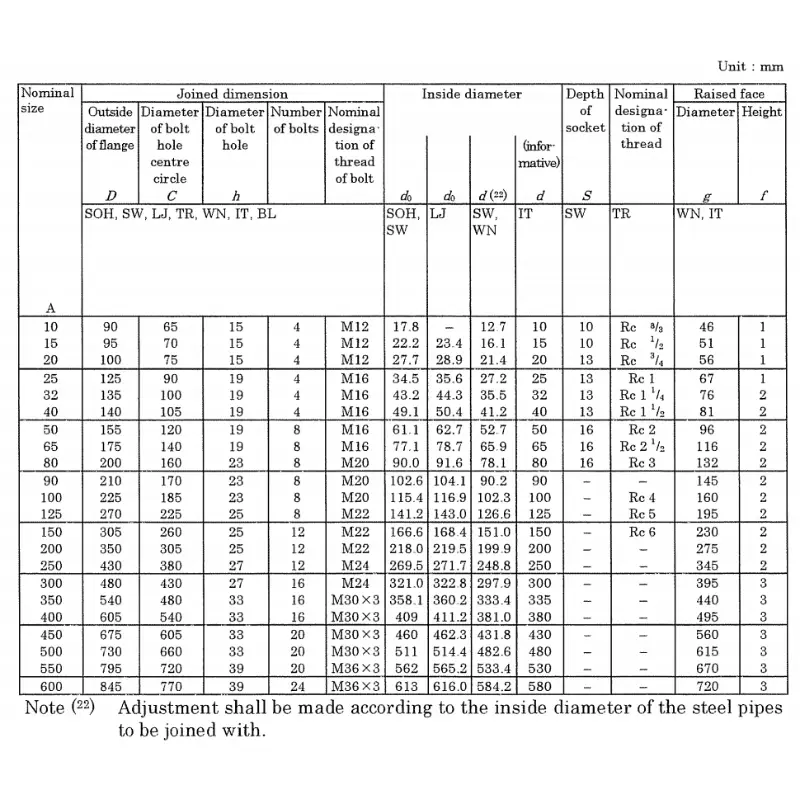
Specifications of flanges made according to JIS B2220
JIS 5K. flange standard specification
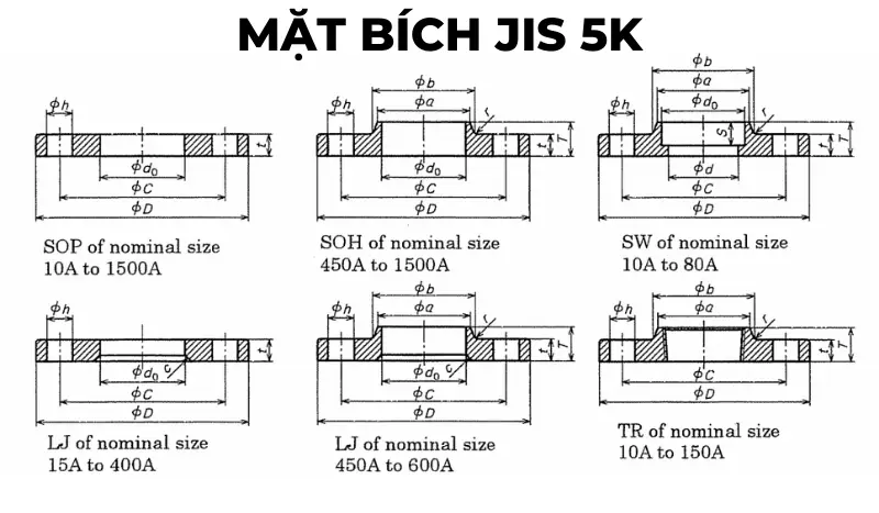
JIS 5K. flange drawing

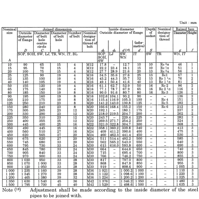
JIS 5K. Flange Specifications
JIS 10K. Flange Standard Specifications
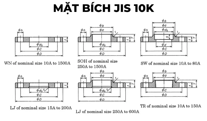
JIS 10K. Flange Drawing
JIS 10K. Flange Specifications
JIS 16K. flange standard specification
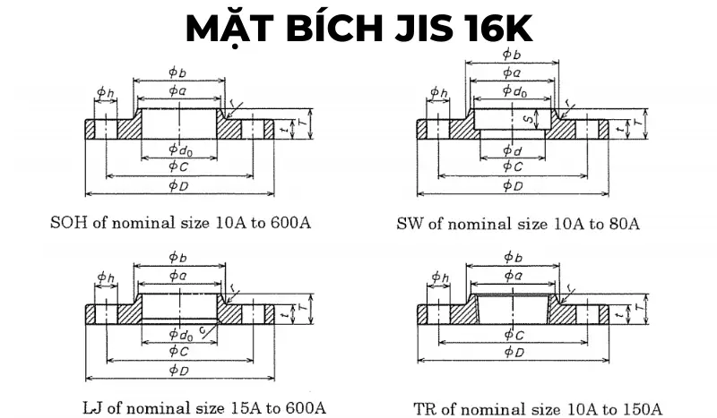
JIS 16K. flange drawing
16K. JIS Flange Specifications
JIS 20K. flange standard specification

20K. JIS flange drawing

20K. JIS Flange Specification
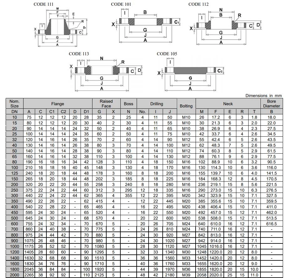
Specifications of flanges made according to DIN. standards
DIN 2576 – PN6. flange standard specification
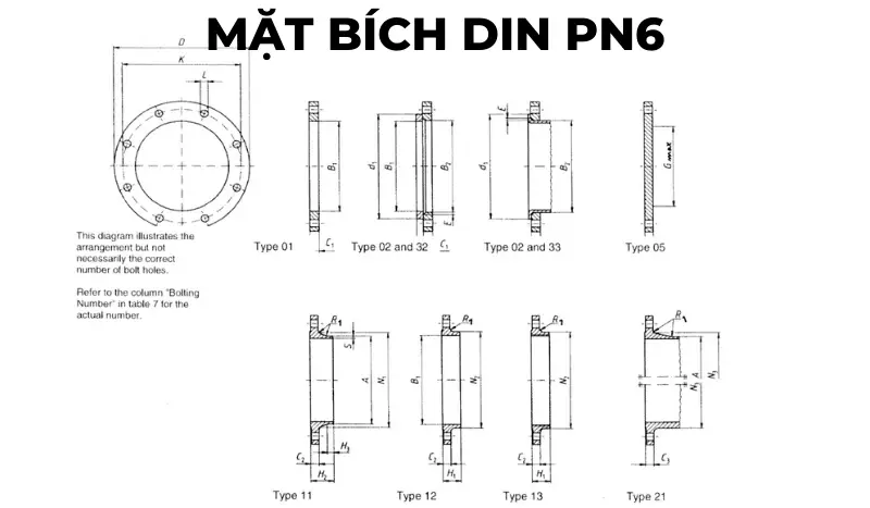
DIN PN6. flange drawing
DIN PN6. Flange Specification Table
| DN | LINK DETAILS | OUTER DIAMETER OF THE WELDING | DIAMETER HOLE | FLANGE THICKNESS | BEVELED FACE | FOR THICK CONNECTORS | WELDING DIAMETER | LENGTH | DIAMETER OF WELDING NECKLINE | CONNECTOR ANGLE | WELDING NECK THICKNESS | |||||||||||
|---|---|---|---|---|---|---|---|---|---|---|---|---|---|---|---|---|---|---|---|---|---|---|
| Outer Diameter | Diameter of Bolt circle | Bolt Hole Diameter | Bolt | |||||||||||||||||||
| D | K | L | Quantity | Size | A | B1 | B2 | C1 | C2 C3 |
C4 | E | F | G max | H1 | H2 | H3 | N1 | N2 | N3 | R1 | S | |
| Flange type | ||||||||||||||||||||||
| 01, 02, 05, 11, 12, 13, 21 | 11 21b |
01 12 32 |
2 | 01 02 |
11 12 13 21 |
5 | 2 | 32 | 5 | 12 13 |
11 | 11 | 11 | 12 13 |
21 | 11 12 13 21 |
11 | |||||
| 10 | 75 | 50 | 11 | 4 | M10 | 17,2 | 18 | 21 | 12 | 12 | 12 | 3 | 10 | – | 20 | 28 | 6 | 26 | 25 | 20 | 4 | 1,8 |
| 15 | 80 | 55 | 11 | 4 | M10 | 21,3 | 22 | 25 | 12 | 12 | 12 | 3 | 10 | – | 20 | 30 | 6 | 30 | 30 | 26 | 4 | 2 |
| 20 | 90 | 65 | 11 | 4 | M10 | 26,9 | 27,5 | 31 | 14 | 14 | 14 | 4 | 10 | – | 24 | 32 | 6 | 38 | 40 | 34 | 4 | 2,3 |
| 25 | 100 | 75 | 11 | 4 | M10 | 33,7 | 34,5 | 38 | 14 | 14 | 14 | 4 | 10 | – | 24 | 35 | 6 | 42 | 50 | 44 | 4 | 2,6 |
| 32 | 120 | 90 | 14 | 4 | M12 | 42,4 | 43,5 | 46 | 16 | 14 | 14 | 5 | 10 | – | 26 | 35 | 6 | 55 | 60 | 54 | 6 | 2,6 |
| 40 | 130 | 100 | 14 | 4 | M12 | 48,3 | 49,5 | 53 | 16 | 14 | 14 | 5 | 10 | – | 26 | 38 | 7 | 62 | 70 | 64 | 6 | 2,6 |
| 50 | 140 | 110 | 14 | 4 | M12 | 60,3 | 61,5 | 65 | 16 | 14 | 14 | 5 | 12 | – | 28 | 38 | 8 | 74 | 80 | 74 | 6 | 2,9 |
| 65 | 160 | 130 | 14 | 4 | M12 | 76,1 | 77,5 | 81 | 16 | 14 | 14 | 6 | 12 | 55 | 32 | 38 | 9 | 88 | 100 | 94 | 6 | 2,9 |
| 80 | 190 | 150 | 18 | 4 | M16 | 88,9 | 90,5 | 94 | 18 | 16 | 16 | 6 | 12 | 70 | 34 | 42 | 10 | 102 | 110 | 110 | 8 | 3,2 |
| 100 | 210 | 170 | 18 | 4 | M16 | 114,3 | 116 | 120 | 18 | 16 | 16 | 6 | 14 | 90 | 40 | 45 | 10 | 130 | 130 | 130 | 8 | 3,6 |
| 125 | 240 | 200 | 18 | 8 | M16 | 139,7 | 141,5 | 145 | 20 | 18 | 18 | 6 | 14 | 115 | 44 | 48 | 10 | 155 | 160 | 160 | 8 | 4 |
| 150 | 265 | 225 | 18 | 8 | M16 | 168,3 | 170,5 | 174 | 20 | 18 | 18 | 6 | 14 | 140 | 44 | 48 | 12 | 184 | 185 | 182 | 10 | 4,5 |
| 200 | 320 | 280 | 18 | 8 | M16 | 219,1 | 221,5 | 226 | 22 | 20 | 20 | 6 | 16 | 190 | 44 | 55 | 15 | 236 | 240 | 238 | 10 | 6,3 |
| 250 | 375 | 335 | 18 | 12 | M16 | 273 | 276,5 | 281 | 24 | 22 | 22 | 8 | 18 | 235 | 44 | 60 | 15 | 290 | 295 | 284 | 12 | 6,3 |
| 300 | 440 | 395 | 22 | 12 | M20 | 323,9 | 327,5 | 333 | 24 | 22 | 22 | 8 | 18 | 285 | 44 | 62 | 15 | 342 | 355 | 342 | 12 | 7,1 |
| 350 | 490 | 445 | 22 | 12 | M20 | 355,6 | 359,5 | 365 | 26 | 22 | 22 | 8 | 18 | 330 | – | 62 | 15 | 385 | – | 392 | 12 | 7,1 |
| 400 | 540 | 495 | 22 | 16 | M20 | 406,4 | 411 | 416 | 28 | 22 | 22 | 8 | 20 | 380 | – | 65 | 15 | 438 | – | 442 | 12 | 7,1 |
| 450 | 595 | 550 | 22 | 16 | M20 | 457 | 462 | 467 | 30 | 22 | 24 | 8 | 20 | 425 | – | 65 | 15 | 492 | – | 494 | 12 | 7,1 |
DIN 2576 – PN10. flange standard specification
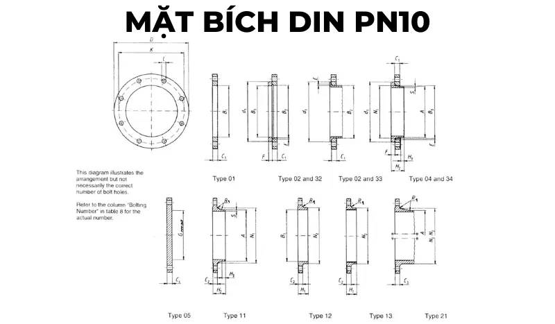
DIN PN10. flange drawing
DIN PN10. Flange Specification Table
| DN | LINK DETAILS | THE OUTER DIAMETER OF THE WELDING NECK | DIAMETER HOLE | FLANGE THICKNESS | BEVELED FACE | CONNECTOR THICKNESS | WELDING FACE DIAMETER | LENGTH | DIAMETER OF WELDING NECKLINE | CONNECTOR ANGLE | WELDING NECK THICKNESS | |||||||||||||
|---|---|---|---|---|---|---|---|---|---|---|---|---|---|---|---|---|---|---|---|---|---|---|---|---|
| Outside Diameter | Diameter of Bolt circle | Bolt Hole Diameter | Bolt | |||||||||||||||||||||
| D | K | L | Quantity | Size | A | B1 | B2 | B3 | C1 | C2 | C3 | C4 | E | F | G max | H1 | H2 | H3 | N1 | N2 | N3 | R1 | S | |
| Flange type | ||||||||||||||||||||||||
| 01, 02, 04, 05, 11, 12, 13, 21 | 11 21 34 |
01 12 32 |
2 | 4 | 01 02 04 |
11 12 13 |
21 | 5 | 02 04 |
32 34 |
5 | 12 13 |
11 14 |
11 14 |
11 14 |
12 13 |
21 | 11 12 13 21 |
11 34 |
|||||
| 10 to 40 | Use pressure class PN40 | |||||||||||||||||||||||
| 50 to 150 | Use pressure class PN16 | |||||||||||||||||||||||
| 200 | 340 | 295 | 22 | 8 | M20 | 219,1 | 221,5 | 226 | 240 | 24 | 24 | 24 | 24 | 6 | 20 | 190 | 44 | 62 | 16 | 234 | 246 | 246 | 10 | 6,3 |
| 250 | 395 | 350 | 22 | 12 | M20 | 273 | 276,5 | 281 | 294 | 26 | 26 | 26 | 26 | 8 | 22 | 235 | 46 | 68 | 16 | 292 | 298 | 298 | 12 | 6,3 |
| 300 | 445 | 400 | 22 | 12 | M20 | 323,9 | 327,5 | 333 | 348 | 26 | 26 | 26 | 26 | 8 | 22 | 285 | 46 | 68 | 16 | 342 | 350 | 348 | 12 | 7,1 |
| 350 | 505 | 460 | 22 | 16 | M20 | 355,6 | 359,5 | 365 | 400 | 28 | 26 | 26 | 26 | 8 | 22 | 330 | 53 | 68 | 16 | 385 | 400 | 408 | 12 | 7,1 |
| 400 | 565 | 515 | 26 | 16 | M24 | 406,4 | 411 | 416 | 450 | 32 | 26 | 26 | 26 | 8 | 24 | 380 | 57 | 72 | 16 | 440 | 456 | 456 | 12 | 7,1 |
| 450 | 615 | 565 | 26 | 20 | M24 | 457 | 462 | 467 | 498 | 36 | 28 | 28 | 28 | 8 | 24 | 425 | 63 | 72 | 16 | 488 | 502 | 502 | 12 | 7,1 |
| 500 | 670 | 620 | 26 | 20 | M24 | 508 | 513,5 | 519 | 550 | 38 | 28 | 28 | 28 | 8 | 26 | 475 | 67 | 75 | 16 | 542 | 559 | 559 | 12 | 7,1 |
| 600 | 780 | 725 | 30 | 20 | M27 | 610 | 616,5 | 622 | 650 | 42 | 28 | 34 | 34 | 8 | 26 | 575 | 75 | 80 | 18 | 642 | 658 | 658 | 12 | 7,1 |
| 700 | 895 | 840 | 30 | 24 | M27 | 711 | 30 | 34 | 38 | 670 | 80 | 18 | 746 | 772 | 12 | 8 | ||||||||
| 800 | 1015 | 950 | 33 | 24 | M30 | 813 | 32 | 36 | 42 | 770 | 90 | 18 | 850 | 876 | 12 | 8 | ||||||||
| 900 | 1115 | 1050 | 33 | 28 | M30 | 914 | 34 | 38 | 46 | 860 | 95 | 20 | 950 | 976 | 12 | 10 | ||||||||
| 1000 | 1230 | 1160 | 36 | 28 | M33 | 1016 | 34 | 38 | 52 | 960 | 95 | 20 | 1052 | 1080 | 16 | 10 | ||||||||
| 1200 | 1455 | 1380 | 39 | 32 | M36 | 1219 | 38 | 44 | 60 | 1160 | 115 | 25 | 1256 | 1292 | 16 | 11 | ||||||||
| 1400 | 1675 | 1590 | 42 | 36 | M39 | 1422 | 42 | 48 | 120 | 25 | 1460 | 1496 | 16 | 12 | ||||||||||
| 1600 | 1915 | 1820 | 48 | 40 | M45 | 1626 | 46 | 52 | 130 | 25 | 1666 | 1712 | 16 | 14 | ||||||||||
| 1800 | 2115 | 2020 | 48 | 44 | M45 | 1829 | 50 | 56 | 140 | 30 | 1868 | 1910 | 16 | 15 | ||||||||||
| 2000 | 2325 | 2230 | 48 | 48 | M45 | 2032 | 54 | 60 | 150 | 30 | 2072 | 2120 | 16 | 16 | ||||||||||
| 2200 | 2550 | 2440 | 56 | 52 | M52 | 2235 | 58 | 160 | 35 | 2275 | 18 | 18 | ||||||||||||
| 2400 | 2760 | 2650 | 56 | 56 | M52 | 2438 | 62 | 170 | 35 | 2478 | 18 | 20 | ||||||||||||
| 2600 | 2960 | 2850 | 56 | 60 | M52 | 2620 | 66 | 180 | 40 | 2680 | 18 | 22 | ||||||||||||
| 2800 | 3180 | 3070 | 56 | 64 | M52 | 2820 | 70 | 190 | 40 | 2882 | 18 | 22 | ||||||||||||
| 3000 | 3405 | 3290 | 62 | 68 | M56 | 3020 | 75 | 200 | 45 | 3085 | 18 | 24 | ||||||||||||
DIN 2544 – PN16. flange standard specification

DIN PN16. flange drawing
DIN PN16. Flange Specification Table
| DN | LINK DETAILS | THE OUTER DIAMETER OF THE WELDING NECK | DIAMETER HOLE | FLANGE THICKNESS | BEVELED FACE | CONNECTOR THICKNESS | WELDING FACE DIAMETER | LENGTH | DIAMETER OF WELDING NECKLINE | CONNECTOR ANGLE | WELDING NECK THICKNESS | |||||||||||||
|---|---|---|---|---|---|---|---|---|---|---|---|---|---|---|---|---|---|---|---|---|---|---|---|---|
| Outside Diameter | Diameter of Bolt circle | Bolt Hole Diameter | Bolt | |||||||||||||||||||||
| D | K | L | Quantity | Size | A | B1 | B2 | B3 | C1 | C2 | C3 | C4 | E | F | G max | H1 | H2 | H3 | N1 | N2 | N3 | R1 | S | |
| Flange type | ||||||||||||||||||||||||
| 01, 02, 04, 05, 11, 12, 13, 21 | 11 21 34 |
01 12 32 |
2 | 4 | 01 02 04 |
11 12 13 |
21 | 5 | 02 04 |
32 34 |
5 | 12 13 |
11 14 |
11 14 |
11 14 |
12 13 |
21 | 11 12 13 21 |
11 34 |
|||||
| 10 to 40 | Use pressure class PN40 | |||||||||||||||||||||||
| 50 | 165 | 125 | 18 | 4 | M16 | 60,3 | 61,5 | 65 | 77 | 19 | 18 | 18 | 18 | 5 | 16 | 28 | 45 | 8 | 74 | 84 | 84 | 5 | 2,9 | |
| 65 | 185 | 145 | 18 | 8 | M16 | 76,1 | 77,5 | 81 | 96 | 20 | 18 | 18 | 18 | 6 | 16 | 55 | 32 | 45 | 10 | 92 | 104 | 104 | 6 | 2,9 |
| 80 | 200 | 160 | 18 | 8 | M16 | 88,9 | 90,5 | 94 | 108 | 20 | 20 | 20 | 20 | 6 | 16 | 70 | 34 | 50 | 10 | 105 | 118 | 120 | 6 | 3,2 |
| 100 | 220 | 180 | 18 | 8 | M16 | 114,3 | 116 | 120 | 134 | 22 | 20 | 20 | 20 | 6 | 18 | 90 | 40 | 52 | 12 | 131 | 140 | 140 | 8 | 3,6 |
| 125 | 250 | 210 | 18 | 8 | M16 | 139,7 | 141,5 | 145 | 162 | 22 | 22 | 22 | 22 | 6 | 18 | 115 | 44 | 55 | 12 | 156 | 168 | 170 | 8 | 4 |
| 150 | 285 | 240 | 22 | 8 | M20 | 168,3 | 170,5 | 174 | 188 | 24 | 22 | 22 | 22 | 6 | 20 | 140 | 44 | 55 | 12 | 184 | 195 | 190 | 10 | 4,5 |
| 200 | 340 | 295 | 22 | 12 | M20 | 219,1 | 221,5 | 226 | 240 | 26 | 24 | 24 | 24 | 6 | 20 | 190 | 44 | 62 | 16 | 235 | 246 | 246 | 10 | 6,3 |
| 250 | 405 | 355 | 26 | 12 | M24 | 273 | 276,5 | 281 | 294 | 29 | 26 | 26 | 26 | 8 | 22 | 235 | 46 | 70 | 16 | 292 | 298 | 296 | 12 | 6,3 |
| 300 | 460 | 410 | 26 | 12 | M24 | 323,9 | 327,5 | 33 | 348 | 32 | 28 | 28 | 28 | 8 | 24 | 285 | 46 | 78 | 16 | 344 | 350 | 350 | 12 | 7,1 |
| 350 | 520 | 470 | 26 | 16 | M24 | 355,6 | 359 | 365 | 400 | 35 | 30 | 30 | 30 | 8 | 26 | 330 | 57 | 82 | 16 | 390 | 400 | 410 | 12 | 8 |
| 400 | 580 | 525 | 30 | 16 | M27 | 406,4 | 411 | 416 | 454 | 38 | 32 | 32 | 32 | 8 | 28 | 380 | 63 | 85 | 16 | 445 | 456 | 458 | 12 | 8 |
| 450 | 640 | 585 | 30 | 20 | M27 | 457 | 462 | 467 | 500 | 42 | 40 | 40 | 40 | 8 | 30 | 425 | 68 | 87 | 16 | 490 | 502 | 516 | 12 | 8 |
| 500 | 715 | 650 | 33 | 20 | M30 | 508 | 513,5 | 510 | 556 | 46 | 44 | 44 | 44 | 8 | 32 | 475 | 73 | 90 | 16 | 548 | 559 | 576 | 12 | 8 |
| 600 | 840 | 770 | 36 | 20 | M33 | 610 | 616,5 | 622 | 660 | 52 | 54 | 54 | 54 | 8 | 32 | 575 | 83 | 95 | 18 | 652 | 658 | 690 | 12 | 8,8 |
| 700 | 910 | 840 | 36 | 24 | M33 | 711 | 36 | 42 | 48 | 670 | 83 | 100 | 18 | 755 | 760 | 760 | 12 | 8,8 | ||||||
| 800 | 1025 | 950 | 39 | 24 | M36 | 813 | 38 | 42 | 52 | 770 | 90 | 105 | 20 | 855 | 864 | 862 | 12 | 10 | ||||||
| 900 | 1125 | 1050 | 39 | 28 | M36 | 914 | 40 | 44 | 58 | 860 | 94 | 110 | 20 | 955 | 968 | 962 | 12 | 10 | ||||||
| 1000 | 1255 | 1170 | 42 | 28 | M39 | 1016 | 42 | 46 | 64 | 960 | 100 | 120 | 22 | 1058 | 1072 | 1070 | 16 | 10 | ||||||
| 1200 | 1485 | 1390 | 48 | 32 | M45 | 1219 | 48 | 52 | 76 | 1160 | 130 | 30 | 1262 | 1282 | 16 | 12,5 | ||||||||
| 1400 | 1685 | 1590 | 48 | 36 | M45 | 1422 | 52 | 58 | 1346 | 145 | 30 | 1465 | 1482 | 16 | 14,2 | |||||||||
| 1600 | 1930 | 1820 | 56 | 40 | M52 | 1626 | 58 | 64 | 1546 | 160 | 35 | 1668 | 1696 | 16 | 16 | |||||||||
| 1800 | 2130 | 2020 | 56 | 44 | M52 | 1829 | 62 | 68 | 1746 | 170 | 35 | 1870 | 1896 | 16 | 17,5 | |||||||||
| 2000 | 2345 | 2230 | 62 | 48 | M56 | 2032 | 66 | 70 | 1950 | 180 | 40 | 2072 | 2100 | 16 | 20 | |||||||||
DIN 2544 – PN25. flange standard specification
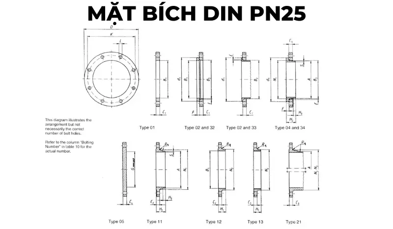 DIN PN25. flange drawing
DIN PN25. Flange Specification Table
| DN | LINK DETAILS | THE OUTER DIAMETER OF THE WELDING NECK | DIAMETER HOLE | FLANGE THICKNESS | BEVELED FACE | CONNECTOR THICKNESS | WELDING FACE DIAMETER | LENGTH | DIAMETER OF WELDING NECKLINE | CONNECTOR ANGLE | WELDING NECK THICKNESS | |||||||||||||
|---|---|---|---|---|---|---|---|---|---|---|---|---|---|---|---|---|---|---|---|---|---|---|---|---|
| Outside Diameter | Diameter of Bolt circle | Bolt Hole Diameter | Bolt | |||||||||||||||||||||
| D | K | L | Quantity | Size | A | B1 | B2 | B3 | C1 | C2 | C3 | C4 | E | F | G max | H1 | H2 | H3 | N1 | N2 | N3 | R1 | S | |
| Flange type | ||||||||||||||||||||||||
| 01, 02, 04, 05, 11, 12, 13, 21 | 11 21 34 |
01 12 32 |
2 | 4 | 01 02 04 |
11 12 13 |
21 | 5 | 02 04 |
32 34 |
5 | 12 13 |
11 14 |
11 14 |
11 14 |
12 13 |
21 | 11 12 13 21 |
11 34 |
|||||
| 10 to 150 | Use pressure class PN40 | |||||||||||||||||||||||
| 200 | 360 | 310 | 26 | 12 | M24 | 219,1 | 221,5 | 226 | 250 | 32 | 30 | 30 | 30 | 6 | 26 | 190 | 52 | 80 | 16 | 244 | 256 | 252 | 10 | 6,3 |
| 250 | 425 | 370 | 30 | 12 | M27 | 273 | 276,5 | 281 | 302 | 35 | 32 | 32 | 32 | 8 | 26 | 235 | 60 | 88 | 18 | 298 | 310 | 304 | 12 | 7,1 |
| 300 | 485 | 430 | 30 | 16 | M27 | 323,9 | 327,5 | 333 | 356 | 38 | 34 | 34 | 34 | 8 | 28 | 285 | 67 | 92 | 18 | 352 | 364 | 364 | 12 | 8 |
| 350 | 555 | 490 | 33 | 16 | M30 | 355,6 | 359,5 | 365 | 408 | 42 | 38 | 38 | 38 | 8 | 32 | 332 | 72 | 100 | 20 | 398 | 418 | 418 | 12 | 8 |
| 400 | 620 | 550 | 36 | 16 | M33 | 406,4 | 411 | 416 | 462 | 46 | 40 | 40 | 40 | 8 | 34 | 380 | 78 | 110 | 20 | 452 | 472 | 472 | 12 | 8,8 |
| 450 | 670 | 600 | 36 | 20 | M33 | 457 | 462 | 467 | 510 | 50 | 46 | 46 | 46 | 8 | 36 | 425 | 84 | 110 | 20 | 500 | 520 | 520 | 12 | 8,8 |
| 500 | 730 | 660 | 36 | 20 | M33 | 508 | 513,5 | 519 | 568 | 56 | 48 | 48 | 48 | 8 | 38 | 475 | 90 | 125 | 20 | 558 | 580 | 580 | 12 | 10 |
| 600 | 845 | 770 | 39 | 20 | M36 | 610 | 616,5 | 622 | 670 | 68 | 58 | 58 | 58 | 8 | 40 | 575 | 100 | 125 | 20 | 660 | 684 | 684 | 12 | 11 |
| 700 | 960 | 875 | 42 | 24 | M39 | 711 | 46 | 50 | 125 | 20 | 760 | 780 | 12 | 12,5 | ||||||||||
| 800 | 1085 | 990 | 48 | 24 | M45 | 813 | 50 | 54 | 135 | 22 | 864 | 882 | 12 | 14,2 | ||||||||||
| 900 | 1185 | 1090 | 48 | 28 | M45 | 914 | 54 | 58 | 145 | 24 | 968 | 982 | 12 | 16 | ||||||||||
| 1000 | 1320 | 1210 | 56 | 28 | M52 | 1016 | 58 | 62 | 155 | 24 | 1070 | 1086 | 16 | 17,5 | ||||||||||
| 1200 | 1530 | 1420 | 56 | 32 | M52 | 1219 | 70 | 1296 | 18 | |||||||||||||||
| 1400 | 1755 | 1640 | 62 | 36 | M56 | 1422 | 76 | 1508 | 18 | |||||||||||||||
| 1600 | 1975 | 1860 | 62 | 40 | M56 | 1626 | 84 | 1726 | 20 | |||||||||||||||
| 1800 | 2195 | 2070 | 70 | 44 | M64 | 1829 | 90 | 1920 | 20 | |||||||||||||||
| 2000 | 2425 | 2300 | 70 | 48 | M64 | 2032 | 96 | 2150 | 20 | |||||||||||||||
DIN 2544 – PN40. flange standard specification
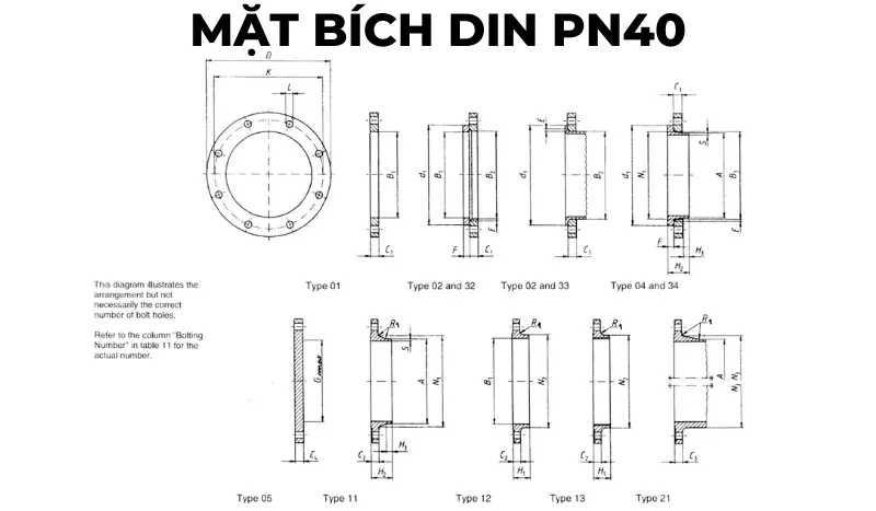 DIN PN40. flange drawing
DIN PN40. Flange Specification Table
| DN | LINK DETAILS | OUTSIDE DIAMETER OF THE WELDING NECK | DIAMETER HOLE | FLANGE THICKNESS | BEVELED FACE | CONNECTOR THICKNESS | WELDING FACE DIAMETER | LENGTH | DIAMETER OF WELDING NECKLINE | CONNECTOR ANGLE | WELDING NECK THICKNESS | |||||||||||||
|---|---|---|---|---|---|---|---|---|---|---|---|---|---|---|---|---|---|---|---|---|---|---|---|---|
| Outside Diameter | Diameter of Bolt circle | Bolt Hole Diameter | Bolt | |||||||||||||||||||||
| D | K | L | Quantity | Size | A | B1 | B2 | B3 | C1 | C2 | C3 | C4 | E | F | G max | H1 | H2 | H3 | N1 | N2 | N3 | R1 | S | |
| Flange type | ||||||||||||||||||||||||
| 01, 02, 04, 05, 11, 12, 13, 21 | 11 21 34 |
01 12 32 |
2 | 4 | 01 02 04 |
11 12 13 |
21 | 5 | 02 04 |
32 34 |
5 | 12 13 |
11 14 |
11 14 |
11 14 |
12 13 |
21 | 11 12 13 21 |
11 34 |
|||||
| 10 | 90 | 60 | 14 | 4 | M12 | 17,2 | 18 | 21 | 31 | 14 | 16 | 16 | 16 | 3 | 12 | 22 | 35 | 6 | 28 | 30 | 28 | 4 | 1,8 | |
| 15 | 95 | 65 | 14 | 4 | M12 | 21,3 | 22 | 25 | 35 | 14 | 16 | 16 | 16 | 3 | 12 | 22 | 38 | 6 | 32 | 35 | 32 | 4 | 2 | |
| 20 | 105 | 75 | 14 | 4 | M12 | 26,9 | 27,5 | 31 | 42 | 16 | 18 | 18 | 18 | 4 | 14 | 26 | 40 | 6 | 40 | 45 | 40 | 4 | 2,3 | |
| 25 | 115 | 85 | 14 | 4 | M12 | 33,7 | 34,5 | 38 | 49 | 16 | 18 | 18 | 18 | 4 | 14 | 28 | 40 | 6 | 46 | 52 | 50 | 4 | 2,6 | |
| 32 | 140 | 100 | 18 | 4 | M16 | 42,4 | 43,5 | 47 | 59 | 18 | 18 | 18 | 18 | 5 | 14 | 30 | 42 | 6 | 56 | 60 | 60 | 6 | 2,6 | |
| 40 | 150 | 110 | 18 | 4 | M16 | 48,3 | 49,5 | 53 | 67 | 18 | 18 | 18 | 18 | 5 | 14 | 32 | 45 | 7 | 64 | 70 | 70 | 6 | 2,6 | |
| 50 | 165 | 125 | 18 | 4 | M16 | 60,3 | 61,5 | 65 | 77 | 20 | 20 | 20 | 20 | 5 | 16 | 34 | 48 | 8 | 75 | 84 | 84 | 6 | 2,9 | |
| 65 | 185 | 145 | 18 | 8 | M16 | 76,1 | 77,5 | 81 | 96 | 22 | 22 | 22 | 22 | 6 | 16 | 55 | 38 | 52 | 10 | 90 | 104 | 104 | 6 | 2,9 |
| 80 | 200 | 160 | 18 | 8 | M16 | 88,9 | 90,5 | 94 | 114 | 24 | 24 | 24 | 24 | 6 | 18 | 70 | 40 | 58 | 12 | 105 | 118 | 120 | 8 | 3,2 |
| 100 | 235 | 190 | 22 | 8 | M20 | 114,3 | 116 | 120 | 138 | 26 | 24 | 24 | 24 | 6 | 20 | 90 | 44 | 65 | 12 | 134 | 145 | 142 | 8 | 3,6 |
| 125 | 270 | 220 | 26 | 8 | M24 | 139,7 | 141,5 | 145 | 166 | 28 | 26 | 26 | 26 | 6 | 22 | 115 | 48 | 68 | 12 | 162 | 170 | 162 | 8 | 4 |
| 150 | 300 | 250 | 26 | 8 | M24 | 168,3 | 170,5 | 174 | 194 | 30 | 28 | 28 | 28 | 6 | 24 | 140 | 52 | 75 | 12 | 192 | 200 | 192 | 10 | 4,5 |
| 200 | 375 | 320 | 30 | 12 | M27 | 219,1 | 221,5 | 226 | 250 | 36 | 34 | 34 | 36 | 6 | 28 | 190 | 52 | 88 | 16 | 244 | 260 | 254 | 10 | 6,3 |
| 250 | 450 | 385 | 33 | 12 | M30 | 273 | 276,5 | 281 | 312 | 38 | 38 | 38 | 38 | 8 | 30 | 235 | 60 | 105 | 18 | 306 | 312 | 312 | 12 | 7,1 |
| 300 | 515 | 450 | 33 | 16 | M30 | 323,9 | 327,5 | 333 | 368 | 42 | 42 | 42 | 42 | 8 | 34 | 285 | 67 | 115 | 18 | 362 | 380 | 378 | 12 | 8 |
| 350 | 580 | 510 | 36 | 16 | M33 | 355,6 | 359,5 | 365 | 418 | 46 | 46 | 46 | 46 | 8 | 36 | 330 | 72 | 125 | 20 | 408 | 424 | 432 | 12 | 8,8 |
| 400 | 660 | 585 | 39 | 16 | M36 | 406,4 | 411 | 416 | 472 | 50 | 50 | 50 | 50 | 8 | 42 | 380 | 78 | 135 | 20 | 462 | 478 | 498 | 12 | 11 |
| 450 | 685 | 610 | 39 | 20 | M36 | 457 | 462 | 467 | 510 | 57 | 57 | 57 | 57 | 8 | 46 | 425 | 84 | 135 | 20 | 500 | 522 | 522 | 12 | 12,5 |
| 500 | 755 | 670 | 42 | 20 | M39 | 508 | 513,5 | 519 | 572 | 57 | 57 | 57 | 57 | 8 | 50 | 475 | 90 | 140 | 20 | 562 | 576 | 576 | 12 | 14,2 |
| 600 | 890 | 795 | 48 | 20 | M45 | 610 | 616,5 | 622 | 676 | 72 | 72 | 72 | 72 | 8 | 54 | 575 | 100 | 150 | 20 | 666 | 686 | 686 | 12 | 16 |
Specifications for flanges made according to ANSI
Standard Specifications of 150. Series ANSI Flanges
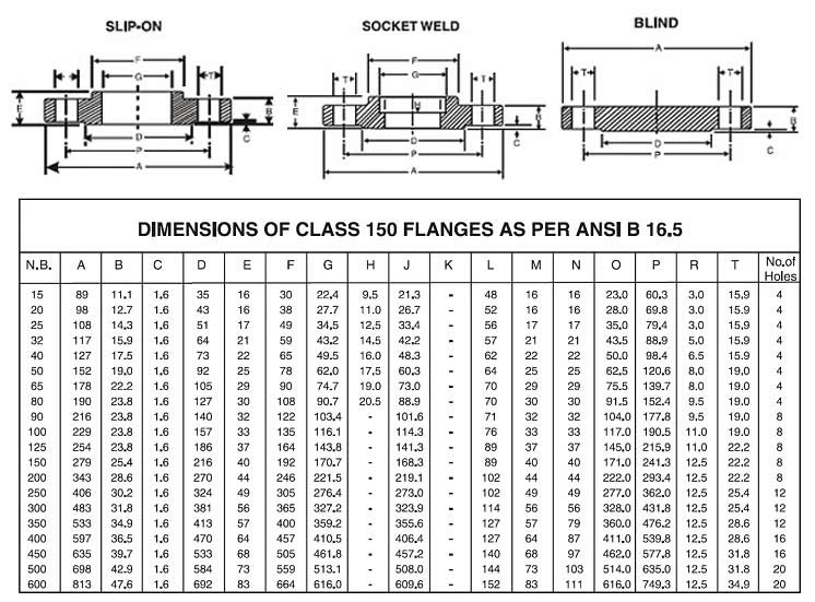
Standard Specifications of the 300. Series ANSI Flanges
 🔥🔥🔥In addition to two lines, 150 & 300 are common goods, ANSI flanges also have other lines 400, 600, 900, 1500, and 2500. You can see more in the table below (Documents are quoted from the standard). ASME/ANSI B16.10/19).
| SERIES | PIPE SIZE (INCH) |
OUTER DIAMETER OF THE FLANGE (MM) |
OUTDOOR DIAMETER OF THE PIPE (MM) |
NUMBER OF BOLTS | DIAMETER BOLTS (MM) |
BOLT CIRCLE (MM) |
|---|---|---|---|---|---|---|
| 400 Series | 1/2 | 57,2 | 21,3 | 4,0 | 15,9 | 34,9 |
| 3/4 | 85,7 | 26,7 | 4,0 | 19,1 | 69,9 | |
| 1 | 79,4 | 33,5 | 4,0 | 19,1 | 63,5 | |
| 1-1 / 4 | 120,7 | 42,2 | 4,0 | 19,1 | 54,0 | |
| 1-1 / 2 | 149,2 | 48,3 | 4,0 | 22,2 | 88,9 | |
| 2 | 139,7 | 60,5 | 8,0 | 19,1 | 127,0 | |
| 2-1 / 2 | 165,1 | 73,2 | 8,0 | 22,2 | 104,8 | |
| 3 | 196,9 | 88,9 | 8,0 | 22,2 | 136,5 | |
| 3-1 / 2 | 228,6 | 101,6 | 8,0 | 25,4 | 171,5 | |
| 4 | 254,0 | 114,3 | 8,0 | 25,4 | 181,0 | |
| 5 | 279,4 | 141,2 | 8,0 | 25,4 | 222,3 | |
| 6 | 292,1 | 168,4 | 12,0 | 25,4 | 238,1 | |
| số 8 | 381,0 | 219,2 | 12,0 | 22,2 | 330,2 | |
| 10 | 419,1 | 273,1 | 16,0 | 19,1 | 374,7 | |
| 12 | 495,3 | 323,9 | 16,0 | 15,9 | 412,8 | |
| 14 | 584,2 | 355,6 | 20,0 | 15,9 | 501,7 | |
| 16 | 622,3 | 406,4 | 20,0 | 12,7 | 546,1 | |
| 18 | 711,2 | 457,2 | 24,0 | 12,7 | 590,6 | |
| 20 | 749,3 | 508,0 | 24,0 | 9,5 | 685,8 | |
| 24 | 914,4 | 609,6 | 24,0 | 3,2 | 812,8 | |
| 600 Series | 1/2 | 57,2 | 21,3 | 4,0 | 15,9 | 34,9 |
| 3/4 | 85,7 | 26,7 | 4,0 | 19,1 | 69,9 | |
| 1 | 79,4 | 33,5 | 4,0 | 19,1 | 63,5 | |
| 1-1/4 | 120,7 | 42,2 | 4,0 | 19,1 | 54,0 | |
| 1-1/2 | 149,2 | 48,3 | 4,0 | 22,2 | 88,9 | |
| 2 | 139,7 | 60,5 | 8,0 | 19,1 | 127,0 | |
| 2-1/2 | 165,1 | 73,2 | 8,0 | 22,2 | 104,8 | |
| 3 | 196,9 | 88,9 | 8,0 | 22,2 | 136,5 | |
| 3-1/2 | 228,6 | 101,6 | 8,0 | 25,4 | 171,5 | |
| 4 | 235,0 | 114,3 | 8,0 | 25,4 | 190,5 | |
| 5 | 330,2 | 141,2 | 8,0 | 19,1 | 241,3 | |
| 6 | 355,6 | 168,4 | 12,0 | 19,1 | 266,7 | |
| 8 | 393,7 | 219,2 | 12,0 | 19,1 | 311,2 | |
| 10 | 508,0 | 273,1 | 16,0 | 15,9 | 431,8 | |
| 12 | 558,8 | 323,9 | 20,0 | 15,9 | 476,3 | |
| 14 | 565,2 | 355,6 | 20,0 | 12,7 | 489,0 | |
| 16 | 685,8 | 406,4 | 20,0 | 9,5 | 565,2 | |
| 18 | 730,3 | 457,2 | 20,0 | 6,4 | 616,0 | |
| 20 | 812,8 | 508,0 | 24,0 | 6,4 | 698,5 | |
| 24 | 939,8 | 609,6 | 24,0 | 50,8 | 838,2 | |
| 900 Series | 1/2 | 82,6 | 21,3 | 4,0 | 22,2 | 69,9 |
| 3/4 | 123,8 | 26,7 | 4,0 | 22,2 | 63,5 | |
| 1 | 104,8 | 33,5 | 4,0 | 25,4 | 101,6 | |
| 1-1/4 | 146,1 | 42,2 | 4,0 | 25,4 | 92,1 | |
| 1-1/2 | 177,8 | 48,3 | 4,0 | 22,2 | 79,4 | |
| 2 | 190,5 | 60,5 | 8,0 | 25,4 | 139,7 | |
| 2-1/2 | 212,7 | 73,2 | 8,0 | 22,2 | 165,1 | |
| 3 | 215,9 | 88,9 | 8,0 | 22,2 | 165,1 | |
| 4 | 266,7 | 114,3 | 8,0 | 19,1 | 222,3 | |
| 5 | 311,2 | 141,2 | 8,0 | 15,9 | 279,4 | |
| 6 | 381,0 | 168,4 | 12,0 | 19,1 | 292,1 | |
| 8 | 444,5 | 219,2 | 12,0 | 12,7 | 368,3 | |
| 10 | 520,7 | 273,1 | 16,0 | 12,7 | 444,5 | |
| 12 | 609,6 | 323,9 | 20,0 | 12,7 | 533,4 | |
| 14 | 628,7 | 355,6 | 20,0 | 9,5 | 558,8 | |
| 16 | 666,8 | 406,4 | 20,0 | 6,4 | 603,3 | |
| 18 | 787,4 | 457,2 | 20,0 | 50,8 | 685,8 | |
| 20 | 819,2 | 508,0 | 20,0 | 47,6 | 723,9 | |
| 24 | 1041,4 | 609,6 | 20,0 | 34,9 | 876,3 | |
| ANSI B16.5 covers only sizes through 24″ | ||||||
| 26 | 1047,8 | 20,0 | 28,6 | 927,1 | ||
| 28 | 1168,4 | 20,0 | 73,0 | 1009,7 | ||
| 30 | 1206,5 | 20,0 | 73,0 | 1047,8 | ||
| 32 | 1276,4 | 20,0 | 66,7 | 1130,3 | ||
| 34 | 1397,0 | 20,0 | 60,3 | 1212,9 | ||
| 36 | 1435,1 | 20,0 | 60,3 | 1251,0 | ||
| 1500 Series | 1/2 | 82,6 | 21,3 | 4,0 | 22,2 | 69,9 |
| 3/4 | 123,8 | 26,7 | 4,0 | 22,2 | 63,5 | |
| 1 | 104,8 | 33,5 | 4,0 | 25,4 | 101,6 | |
| 1-1/4 | 146,1 | 42,2 | 4,0 | 25,4 | 92,1 | |
| 1-1/2 | 177,8 | 48,3 | 4,0 | 22,2 | 79,4 | |
| 2 | 190,5 | 60,5 | 8,0 | 25,4 | 139,7 | |
| 2-1/2 | 212,7 | 73,2 | 8,0 | 22,2 | 165,1 | |
| 3 | 241,3 | 88,9 | 8,0 | 19,1 | 203,2 | |
| 4 | 285,8 | 114,3 | 8,0 | 15,9 | 215,9 | |
| 5 | 336,6 | 141,2 | 8,0 | 9,5 | 266,7 | |
| 6 | 368,3 | 168,4 | 12,0 | 12,7 | 292,1 | |
| 8 | 482,6 | 219,2 | 12,0 | 6,4 | 368,3 | |
| 10 | 584,2 | 273,1 | 12,0 | 50,8 | 482,6 | |
| 12 | 647,7 | 323,9 | 16,0 | 47,6 | 546,1 | |
| 14 | 723,9 | 355,6 | 16,0 | 41,3 | 635,0 | |
| 16 | 800,1 | 406,4 | 16,0 | 34,9 | 666,8 | |
| 18 | 914,4 | 457,2 | 16,0 | 28,6 | 749,3 | |
| 20 | 946,2 | 508,0 | 16,0 | 73,0 | 793,8 | |
| 24 | 1168,4 | 609,6 | 16,0 | 60,3 | 990,6 | |
| 2500 Series | 1/2 | 120,7 | 21,3 | 4,0 | 22,2 | 63,5 |
| 3/4 | 114,3 | 26,7 | 4,0 | 22,2 | 57,2 | |
| 1 | 146,1 | 33,5 | 4,0 | 25,4 | 95,3 | |
| 1-1/4 | 171,5 | 42,2 | 4,0 | 22,2 | 123,8 | |
| 1-1/2 | 203,2 | 48,3 | 4,0 | 19,1 | 108,0 | |
| 2 | 222,3 | 60,5 | 8,0 | 22,2 | 133,4 | |
| 2-1/2 | 241,3 | 73,2 | 8,0 | 19,1 | 158,8 | |
| 3 | 304,8 | 88,9 | 8,0 | 15,9 | 228,6 | |
| 4 | 355,6 | 114,3 | 8,0 | 9,5 | 235,0 | |
| 5 | 393,7 | 141,2 | 8,0 | 3,2 | 285,8 | |
| 6 | 482,6 | 168,4 | 8,0 | 47,6 | 342,9 | |
| 8 | 514,4 | 219,2 | 12,0 | 47,6 | 425,5 | |
| 10 | 647,7 | 273,1 | 12,0 | 34,9 | 527,1 | |
| 12 | 762,0 | 323,9 | 12,0 | 28,6 | 600,1 | |
Flange Standard Specification BS 4504 – EN 1092
BS 4504 PN6. flange standard specification
Specifications of BS 4504 PN10. flange standard

Specifications of BS 4504 PN16. flange standard

Specification of BS 4504 PN25. flange standard

Specifications of standard flange BS 4504 PN40

Application of flange 60.
As Tiger Steel mentioned at the beginning of the article. Then flange 60 is produced mainly for use with 60 pipes.
There are two ways to connect flanges:
- Weld connection: for hollow flanges without internal threads or blind flanges
- Threaded connection: used for hollow flanges with internal threads
You can see flange 60 in fire protection works, and water supply systems of buildings and apartments. Or in pressure equipment and piping assemblies, inside marine vessels.
Hopefully, the knowledge that Tiger Steel provides above will be useful to you. If you need to buy steel flanges, you can contact Tiger Steel. In addition to welding flange products,
Tiger Steel trades in black steel pipes, galvanized steel pipes, black square steels, galvanized Hoa Phat, SeAH, …; cast steel pipe, large diameter steel pipe. Steel pipe fittings of all kinds, fire protection accessories, …